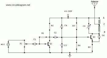
This is a simple, well designed 1.5 Watt FM Transmitter circuit using power transistor 2N2219A. This circuit should be able to cover 1-2 KM range. It use +5-30V power supply to work.
Refer to the above diagram, the input source is an electret condenser microphone (you may try to? use other input sources) and signal gain from the input can be adjusted by using the potentiometer P1. You can easily prepare the PCB by using any PCB editor and apply it to the board by using the ironing method. The coils and the antenna can be designed as a part of the PCB made up of the copper area.
Components List:
| R1=220K R2=4.7K R3,R4=10K R5=100ohm |
C1,C2=4.7uF Electrolytic C3,C4=1nF C5=2-15pF C6=3.3pF |
Q1=BC547C Q2=2N2219A P1=25K MIC=Electret Condenser Type |
P1 act as condenser microphone volume level. For FM, coil will be small. Use thin gauge enamel magnet wire. the diameter of coil will be a couple mm: use ink tube from pen to form, and try 8-12 turns. Small inductance coils make for much guess work.
Good luck.


i need a radio receiver circuit diagram with built-in amplifier that is 3-9volts
i am looking for the components of an fm transmitter the materials needed to set up one or circuit diagrams how to build one i am making is for my assignment and also to widen my knowledge in electronics. thanks to anyone who will email me a shakorbantang@yahoo.co.uk
i am looking for a fm transmitter or circuit diagrams how to build one thanks to anyone who will email me at halfpint2470@yahoo.co.uk
i need 5000watt or 2000watts invertor circuit convert 12v d.c to 220v a.c for small enterprise please try hard for me.isaac522002@yahoo.com
please i need electret mic for my fm transmitter.any one who how i can get should please inform me.amobioke@yahoo.com
in this ckt carrier is not available…..then how we modulate signal
THank’s 4 this fm transmitter circuit.plz.can u help me buy and ship the correct component 4 this work?
Thank’s
Alex.
need a strong AM reciever and transmitter of same freq..
actually, they are available on market… 🙂
2-15pf is not avelebal
Are there more than 75W tx FM circuits? I need it.
Thanks for all emails for diagrams i am now selling transmitter and transmitter kits 1.0watt to 50watt Please email me if you with to buy thanks
please I’ll be happy if you can send me this circuit diagram with the polarities of the capacitors. please Ineed this for my school projects
(+234)8063409127
i was given a project topic to build am fm reciever 100w.my problem is i dont know were to start,wat i need and the components needed to build it.plz cam u help me
i want +ve,-ve of c1,c2 and about coils
mommad786@yahoo.com
i want +ve,-ve of c1,c2 and about coils
this is nothing more than a power oscillator running or using this type of design for anything more than testing within the home is very unwise. the circuit does cause very bad harmonics witch causes RFI on the upper and lower bands. i.e transmitting@100mhz causes RFI @200mhz ,300mhz, 400mhz and carries on the same on the lower bands as well.. aslo with this type of circuit the final transistor(2219) gets too hot causeing the transmission freq to drift -/+ 2-3mhz. i have many designs i have made and still use today. if any one would like a diagram. just let me know mail me dee_stew77@yahoo.co.uk
How do I make this coil Please tell me
Hi emmanuel pls i need 1000w fm transmitter circuit diagram and power amplifier for school assingments. Thinks from emmanuel
send this diagram