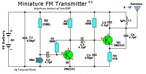
This is a mini FM transmitter built and powered using 2 transistors, designed by Tony van Roon. This small transmitter is simple to build and its transmissions could be picked up on any common FM radio. It possesses a range of approximately 1/4-mile (400 meters) or even more, depending on the line-of-sight, obstructions by big buildings, and so on. It’s excellent for room monitoring, baby listening, nature exploration, and many others.
Components List:
R1,R3 = 100K
R2 = 10K
R4 = 470 ohm
C1,C4 = 470pF
C2,C3 = 4.7uF, 16V, electrolytic
C5,C6 = 4.7pF
C7 = 4-40pF trimmer cap (optional, see text)
L1 = 1uH
Q1,Q2 = 2N2222, NPN transistor
Mic = Electret Microphone
B1 = 9 Volt, Alkaline battery
Nothing critical here. To get a bit of tuning out of the coil you could put a 4-40pF trimmer capacitor (optional) parallel over the 1 uH coil, L1. C1/C4 and C5/C6 are ceramic capacitors, preferably NPO (low noise) types. C2/C3 are electrolytic or can be tantalum types. The antenna is nothing more than a piece of 12″ wire or a piece of piano wire from 6″ to 12″.
Set your FM radio for a clear, black spot in the lower end of the band (88MHz). Then, using a non-conductive/non-metallic trimmer tool, fine-tune this capacitor to find the clearest reception. A little bit testing and patience might be in order.
Almost all of the components values aren’t crucial, so you are able to attempt adjusting them to see what occurs. In the event you determine to substitute transistors with something similar you currently have, it possibly needed alter the collector voltage of Q1 by altering the value of R2 or R3 (because you change transistors, it changes this bias on the base of Q1). It ought to be about 1/2 the power supply voltage (about 4 or 5volts).
Mini FM Transmitter Circuit Notes:
The default for the capacitors kind is ceramic, preferably the npo 1% (low noise) kind or equivalent. But generally almost nothing vital right here. Use any capacitor you’ve laying around, but NO electrolytic or tantalum caps. Only in case you intend to use this circuit outside the house you might wish to choose much more temperature stable capacitors.
To find the signal in your receiver, make certain there’s a signal coming into the microphone, otherwise the circuit will not work. I use an old mechanical alarm clock (you realize, with these two big bells on it). I put this clock by the microphone which picks up the loud tick-tock. I am sure you get the idea… Or you are able to just lightly tap the microphone whilst looking for the location with the signal in your receiver.


I am make this circuit but what is output frequency? Please tell me frequency.my oral on monday please sir
can u plz explain Rx resistor, what is it..?? thanx
ok, the parts list is correct now.. thank you
What rabbishi yaar while circuit shows both the transistors are 2N2222 dut your component list shows 2N3904 , and your circuit shows there are only 4 resistirs (r-4) but your component list shows there are 7 resistors , and there is no discription about Rx. Are you joking my friend ??? How funny , sorry…..