
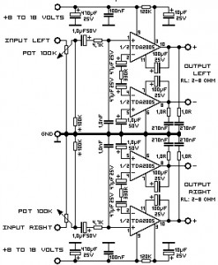
This is the scheme diagram of 20 Watt stereo audio amplifier which use dual IC TDA2005, one IC for left channel and the another one for right channel. Each IC will give you 20 watt output, so the output will be 2×20 Watt. The supply voltage for this circuit is 8VDC to 18VDC, use regulated power supply for better audio output performance.
Use a good quality transformer (of course it wiil be more expensive) to get less noise. It will be another good way to use a sufficient battery to power the circuit. Keep the supply wires as short as possible. Input source should be isolated from the external noises too. It is recommended to use coaxial cable to connect the input audio.
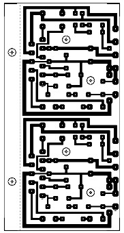
Bottom PCB Layout:
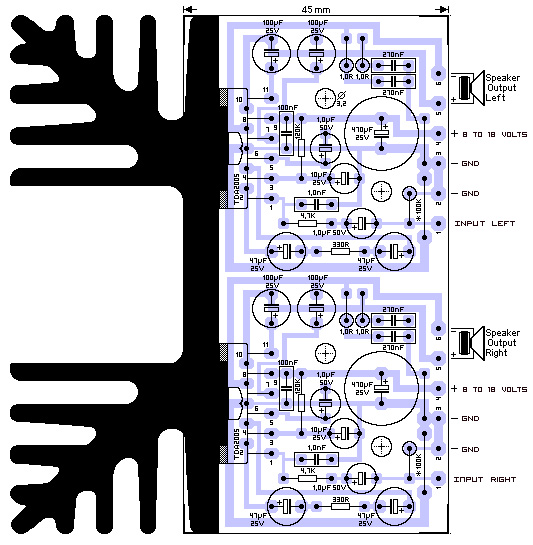
Top PCB Layout and Component Placement:
20 Watt Stereo Audio Amplifier Technical Data:
- Performance of TDA2005M: (for this circuit); At 14.4 V supply voltage: 2 x 20 watts (stereo) into 4 Ohms.
- Distortion: Approx. 0.2% at 4 Watts into 4 ohm load.
- Frequency Range: Approx. 20 Hz to 22 KHz.
- Input Sensitivity: Approx. maximum 150 mV rms.
- Power supply: + 8 to 18 volts, approx. maximum 3.5 Amps per channel.


dear sir, please send me tda 2005 schematic diagram with pcb layout.