
This is the circuit diagram of 230V automatic night lamp based photo resistor to sensing the light environment. When the condition is dark enough, the one or more lamps will be turned on and when the condition is bright enough, then the lamps will be turned off.
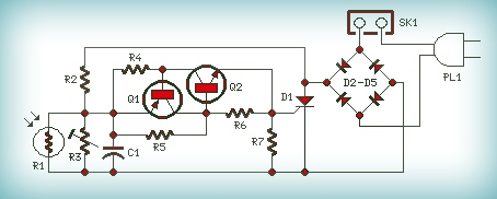
Q1 and Q2 form a trigger device for the SCR, providing short pulses at 100Hz frequency. Pulse duration is set by R2 and C1.
When the light hits? the photo resistor (R1) then it will has very low resistance value, almost shorting C1 and preventing circuit operation. When R1 is in the dark, its resistance value becomes very high thus enabling circuit operation.
Circuit Notes:
- Variable Resistor R3 used for fine setting of operating threshold and R2 value can be raised to 150K maximum.
- Several lamps can be connected in parallel to the circuit, but total power dissipation of the load should not exceed about 300 – 500W.
- PL1 can be omitted and the input mains supply wires connected in parallel to any switch controlling lamps. In this case, if the switch is left open, the circuit will be able to drive the lamps; if the switch is closed, the lamps will illuminate and the circuit will be by-passed.
Parts List:
R1 = Photo resistor (any type)
R2 = 100K 1W Resistor
R3 = 200K 1/2W Trimmer Cermet
R4,R7 = 470R 1/4W Resistors
R5 = 12K 1/4W Resistor
R6 = 1K 1/4W Resistor
C1 = 10nF 63V Polyester Capacitor
D1 = TIC106D 400V 5A SCR
D2-D5 = 1N4007 1000V 1A Diodes
Q1 = BC327 45V 800mA PNP Transistor
Q2 = BC337 45V 800mA NPN Transistor
SK1 = Female Mains socket
PL1 = Male Mains plug & cable
This circuit come from redcircuit.com
Attention! The circuit is directly connected to 230Vac electric mains, then some components in the circuit board are subjected to lethal potential with high risk!. Avoid touching the circuit when plugged and enclose it in a plastic box for security purpose.


Hi there,
I tried this circuit by myself but it doesn’t seem to work properly. Can you please clarify me the connection at D1 and R3.
Thank you