

This 4W Audio Amplifier circuit is powered by 2 pieces of transistor TIP41. The circuit is very simple and incorporates darlington output transistors that will provide more than enough output current than is needed to drive a 3-ohm speaker.
The 4W audio amplifier circuit is very simple and incorporates darlington output transistors that will provide more than enough output current than is needed to drive a 3-ohm speaker. The gain may be pre-set for a variety of input levels, making it suitable for amplifying computer and cassette-deck Line-output levels. The input level is also suitable for use with the TDA7000 receiver. All components are easily to buy on the market. Naturally, the project will be built on a PCB which will also be available separately. Here is the first PCB, assembled and working.
The completed unit is 60mm x 75mm and only 30mm deep. The depth could be reduced to 10mm if the output capacitor is mounted at the speaker and the on-board electrolytics are mounted horisontally. Here are the typical performance figures that may be expected from the finished amplifer using a 3-ohm load with a 13.8-volt supply. I see no reason why the supply voltage cannot be increased a little to obtain more output power:
| Parameter | Minimum | Maximum | Units |
|---|---|---|---|
| Supply voltage | 8 | 15 | volts |
| Output power | – | 5.4 | Watts |
| I/P for full O/P | 30 | 4000 | mV (RMS) |
| Noise O/P no I/P | – | 0.0005 | Volts RMS |
| Supply current (no-signal) | – | 50 | mA |
| Supply Current (Full O/P) | – | 1.9 | Amperes |
| 3dB Frequency Response | 42 | 34000 | Hertz |
| 6dB Frequency Response | 21 | 62000 | Hertz |
| Distortion at 2-watts | – | 0.01 | % (Vgain=10) |
No heatsinking is required for the output transistors when running at a modest output level with either speech or music. A small heatsink should be fitted to the two TIP41 transistors if running a constant tone level. The heatsink could be bolted directly to the TIP41s without electrical isolation if the heatsinks are not going to touch anything. A heatsink with a 15-square surface area is all that is required. Here is the circuit of the amplifier.
The gain of the amplifer is set by selecting the value of the feedback resistor (Rf) on the PCB. The value of Rf is equal to 4700 / (Vgain -1) where Vgain is the voltage gain required. 4-volts RMS is the full-output level. Here is a guide for selecting the resistor.
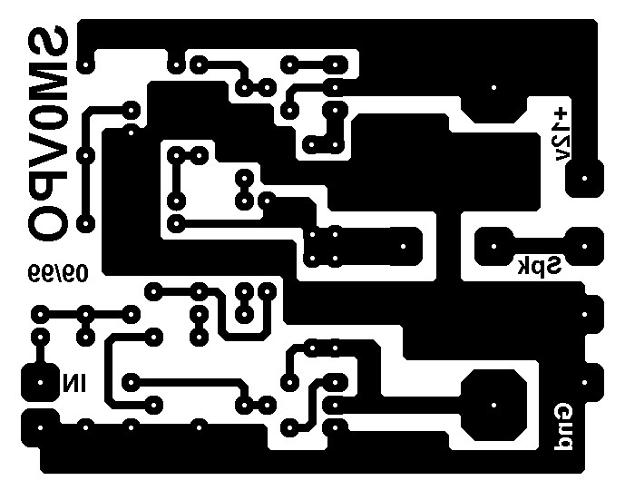
4W Audio Amplifier Bottom PCB Design:
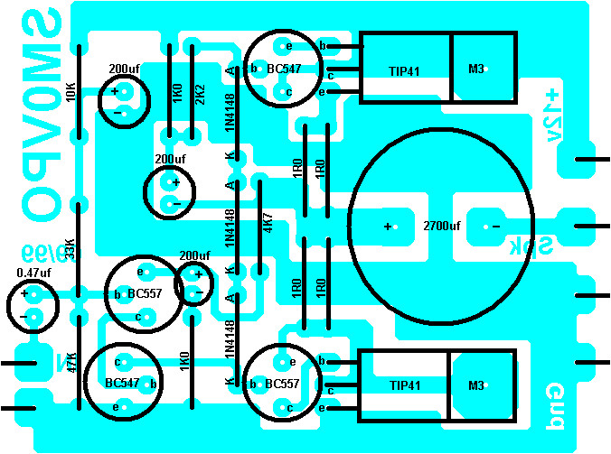
Top PCB Design / Component Placement:


What are the voltage ratings of the capacitors