
This 6V and 12V car battery charger circuit can be automatically charged, quickly and correctly, 6V and 12V batteries. Circuit design is divided into two series of modules that are: power supply module and the main charger module containing the regulator modules and direct current amplifier module.
How the 6V and 12V Car Battery Charger Works
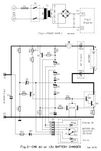
A key factor in the success of the operation of the circuit is the use of good quality transformer [T1] with very good insulation and resistance to short circuits. The Q1 through divider R1-2, of TR1 and R4, functions as a regulated current source. The current through R9 drives power transistors Q5-6, where amplified approximately x2000 times. In an unloaded car battery voltage is about 6V to 8V. With these conditions, the charge current is about 1.2A [regulated by TR1]. When the battery is charging slowly, gradually increases the voltage at its ends. 7V to enter into the D1 conducts. As the battery voltage increases, the voltage decreases at the ends of R3 Q1 made the most conductive. This continues until the current reaches about 6A. Then by means of the voltage drop across R10, is made conductive to Q4. The excess current to the base of Q5 to ground, keeping the load current constant. When the battery is fully charged [14.4V] activated in parallel to the circuit battery, consisting of R6, D8, D2 to D6. At the same time illuminates the D8 indicating that the battery has been fully charged. Simultaneously Q2 is conducting because the voltage drop on R6. The Q3 is conductive and grounded part of the stream at the base of Q5. When the voltage across the battery reaches approximately 15V current at the base of Q5 is very small, so to stop charging the battery. Diodes D5-6 protect the circuit from accidentally installing the battery or short circuits of long duration. The diode D4 protects the circuit from wrong positioning of the battery terminals. Then D9 Led lights showing connection error [ERROR]. Closing switch S2 short the diode D2 [6.8V], now we can charge 6V battery.
6V and 12V Car Battery Charger Component List
| R1-11=1K ohm 0.5W 5% R2=22K ohm 0.5W 5% R3-5-8=10K ohm 0.5W 5% R4=2.2K ohm 0.5W 5% R6=100 ohm 0.5W 5% R7=100K ohm 0.5W 5% R9=470 ohm 0.5W 5% R10=0.08 ohm 10W [2X0.18 ohm parallel] 5W B1=Bridge Rectifier 25A/40V D1-2=6.8V 0.4W Zener D3=4.7V 0.4W Zener D4-6-7=1N4148 D5=18V 0.4W Zener D8=LED 5mm Yellow D9=LED 5mm Red |
Q1-2=BC557 Q3-4=BC547 Q5=BD139 [On Heatsink] Q6=2N3055 [On Heatsink] TR1=4.7K Trimmer Pot. C1=4700uF 40V C2=1uF 25V T1=230Vac//15V 10A Transf. [See Text] F1=Fuse 1A Slo Blo [5X20mm] S1=2X2 Switch 10A per contact S2=1X2 step mini switch J1…4=Flat Pin Connector J5=6pin Connector 2.54mm pin step A=0-10A Ampere meter Batt=12V or 6V Battery |
6V and 12V Car Battery Charger Adjustment
The initial charge current should be adjusted via the TR1 to 1.2A. The adjustment can be done with a 6V battery. Connect in series with the battery a current [maximum 10A]. If there is 6V battery is short-circuited through the ammeter the charger terminals and adjust the TR1 current to 1.2A. When setting the switch S2 should be in the position of 12V, i.e. open. Particular attention should be paid to the accuracy of the diodes D2 and D3 because they protect the battery from overcharging. If the differential voltage is 100mV to go to consider them as acceptable. If you encounter difficulties in the current setting and the TR1 is not enough, you can change the value of the resistor R4, to measure charge current 1.2A. The two parallel resistors constituting R10, should be placed at a distance from the printed and Q5-6, because heated. The bridge B1 and Q5-6 be mounted on heatsink having insulated electrically from this with suitable mica silicone. The bridge B1 and the board in which the circuit is mounted must be connected with short and thick cables, especially where the current is large. lines are also printed on must have the appropriate width [in the project are shown in thicker line]. The construction should be done in a nice metal box, suitable dimensions so there is good ventilation. The construction requires the expertise.
WORK WITH BATTERIES REQUIRE HIGH ATTENTION IN HANDLING BECAUSE THERE IS ALWAYS A RISK OF EXPLOSION.


