
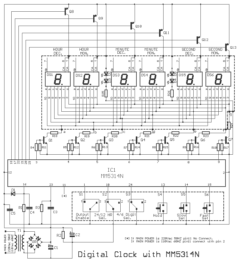
This is the circuit diagram of digital clock based on IC MM5314N. The clock display uses 6 pieces of 7 Segment LED with format HH:MM:SS. The power supply for this circuit already included, so you can connect this circuit directly to the mains. The DC supply is about 5-12V.
Parts List of Digital Clock Circuit:
R1 = 100Kohms
R2 = 47Kohms
R3 = 100Kohms
R4 ….. 10 = 2.2Kohms
R11 ….. 17 = 10Kohms
R18 ….. 24-25-26 = 220 ohmios
R25-26 = 1.2Kohms
C1 = 2200uF 25V
C2 = 100uF 25V
C3 = 18nF 100V
C4-5 = 10nF
D1 = 1N4148
Q1 a Q7 = BC550
Q8 a Q13 = BC560
IC1 = MM5314N ( Discontinue, National Semiconductor)
GR1 = 4X1N4002
T1 = 220V AC/12V 1A
DS1 a DS7 = Display Common Anodo
Datasheet document for digital clock IC MM5314N can be accessed here:
http://www.datasheetspdf.com/PDF/MM5314N/514207/1


Can anyone please send me the pxb layout of this circuit on my mail is prateek839891@gmail.com
I shall be very thankful for her. I need this…