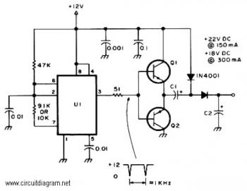
Here is the circuit diagram of active DC voltage doubler which used to increase the DC voltage.
This circuit drives relays of 24 and 18VDC from a 12V power supply. Use this circuit can be work with almost any PNP or NPN power transistor, of course the transistor with specific characteristic similar to the transistor type described in components list.
The timer IC NE555 used to be a multivibrator to generate signal frequency 1KHz and feed to the power transistors for amplification.
Active DC Voltage Doubler Components List:
U1_______: NE555 timer
C1,C2____: 50uF/25V
Q1_______: TIP29, TIP120, TIP61, TIP110, 2N4922, 2N4921
Q2_______: TIP30, TIP125, TIP62, TIP115, TIP125, 2N4918


