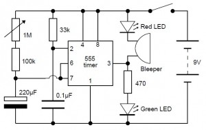
This is a very simple adjustable analog timer circuit diagram. You can build this circuit just for fun, for newbie project or may be…, this circuit could be used to set a time limit when playing games or as an egg-timer in the kitchen.
The circuit will start timing when switched on. The green LED lights to display that timing is in progress. Once the period of time is finished the green LED gets off, the red LED gets on and therefore the bleeper sounds. The interval is set by altering the potensiometer and it could be altered from 1 to about 10 minutes (approximately). Please note that the range of time intervals is only approximate. With ideal parts the maximal time period ought to be 4? minutes, but this is usually extended to about 10 minutes since the 220uF timing capacitor gradually leaks charge. This is actually a problem with all electrolytic capacitors, but some leak more than others. Additionally the real value of electrolytic capacitors can vary by as much as ?30% of their rated value.
Component needed for this adjustable analog timer:
- resistors: 470, 33k, 100k
- variable resistor: 1M
- capacitors: 0.1uF, 220uF 16V radial
- LEDs: red, green
- 555 timer IC
- 8-pin DIL socket for IC
- on/off switch
- battery clip for 9V PP3
- bleeper 9-12V
Download this project in PDF file:
Adjustable analog timer project


