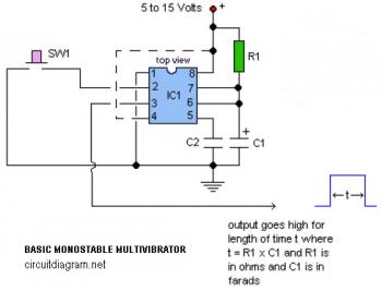
The following diagram is the circuit diagram of basic monostable multivibrator based IC timer 555. This circuit uses only 4 electronic components that are a timer IC, two capacitors and a resistor.
Components List:
A multivibrator is an electronic circuit used to implement a variety of simple two-state systems such as light emitting diodes, timers and flip-flops. The monostable multivibrator will create a condition: in which one of the states is stable, but the other is not?the circuit will flip into the unstable state for a determined period, but will eventually return to the stable state. Such a circuit is useful for creating a timing period of fixed duration in response to some external event. This circuit is also known as a one shot. A common application is in eliminating switch bounce.
R1  : read the explanation
C1  : read the explanation
C2  : 10nF
IC1 : Timer IC LM555
Notes:
- R1 and C1 determine length of output pulse where t = R1 x C1 and R1 is in ohms and C1 is in farads. You may determine the value of R1 and C1 to get the frequency needed.
- Pin 4 is the RESET. Leave it connected to power supply (+V) during normal operation. Bring pin 4 AND pin 2 low at the same time to reset timing cycle.


@edgard you were right dude. i’ve experienced the problem. it is called the pull up resistor that pulls the level of pin 2 to low when the switch is pressed and maintain at high when the switch is open. with the resistor when the switch is open the pin2 floats.
Here is neat explanation on the operation of monostable multivibrator using ic555.
http://yengal-marumugam.blogspot.com/2011/09/monostable-multivibrator.html
This circuit need a resistor of 10k between pin 2 and positive (pin 8)to polarize it.
Without it, the circuit does not work, the out stands always in high level.
(My English is poor, I know it).
Adding this resistor the circuit works properly and is very useful.