
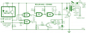
This is the circuit diagram of car audio system anti theft security which can be effectively used to protect and secure your expensive car audio system from stealing. This simple circuit designed based on popular CMOS NAND chip CD4093,.
When the circuit is switched on via switch S1, the indicator LED1 will glow and the circuit state will be in the standby mode. LED inside optocoupler IC1 is lit as the cathode terminal is connected through the car audio (amplifier) body. As a result, the output at pin 3 of gate N1 goes low and disables the rest of the circuit.
Whenever an attempt is made to remove the car audio from its mounting by cutting its connecting wires, the optocoupler immediately turns off, as its LED cathode terminal is hanging. As a result, the oscillator circuit built around gates N2 and N3 is activated and it manages the “on” / “off” timings of the relay via transistor T2. (Relay contacts can be used to energize an emergency beeper, indicator, car horns, etc, if desired.)
Change the values of capacitor C2 to get different “on” / “off” timings for relay RL1 to be “On” / “Off”. With 100uF we get about 5 seconds as “on” and 5 seconds as “off” time. You may make your own experiments as needed.
Gate N4, with its associated components, forms a self-testing circuit. Normally, both of its inputs are in “high” state. However, when one switches off the ignition key, the supply to the car audio is also disconnected. Thus the output of gate N4 jumps to a “high” state and it provides a differentiated short pulse to forward bias transistor T1 for a short duration. (The combination of capacitor C1 and resistor R5 serves as the differentiating circuit.)
As a result, the buzzer in the collector terminal of T1 beeps to announce for a short duration that the safety circuit is intact. This period of “on” ring can be varied by changing the values ??of the capacitor C1 and / or resistor R5.
After construction, fix the LED and buzzer in dashboard as per your requirement and hide switch S1 in a in a convenient place. Then connect lead A to the body of car stereo (not to the body of vehicle) and lead B to its positive lead terminal. Take power supply for the circuit from the car battery directly.
Warning: This design is meant for car audios with negative ground only.


