
This is the circuit diagram of Fuzz Face mods, guitar effect pedal. This is a modified diagram and simpler than the original Fuzz Face diagram.
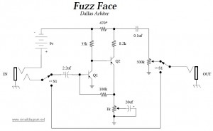
You will find apparently two identical designs of the fuzz face. In one Q1 and Q2 had been PNP germanium AC128 or NKT275 types, in the other they had been NPN sillicon BC108C types. At this moment, depending on which type you decide on to construct will affect several of the some other components. For a PNP type, the schematic is as shown on above, but in case you construct the NPN version, then the 470 ohm resistor which marked by a * need to be changed to 330 ohms, while the battery and all of the polarized capacitors must be reversed.
The original schematic isn’t exaclty what is shown above, it had a pretty complicated switching system that has been simplified (certainly nothing has been missing don”t get worried) and a different grounding setup. Aside from that, the schematic is precise with small variations in components on several units (eg. some component had the 0.1uf capacitor listed as .047uf, which shouldn”t cause a difference as long as you feed a high impedance amplifier). The transistors are difficult to get, the thing to try to find is germanium transistors which has decent gain factor (gain > 80). Note silicon transistors will clip roughly and may possibly not give you good audio output, even though 2n3906 has been mentioned to work.
Download Dallas Arbiter fuzz face schematic in PDF file:


