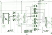
The above diagram is a hierachical priority encoder circuit. Described on wikipedia, priority encoder is a electronic circuit or algorithm that compresses multiple binary inputs into a smaller number of outputs. The output of a priority […]
Category: Digital Circuits
Circuit For Quiz Contest : Electronic Jam
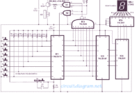
This is the design diagram of electronic jam. This jam circuit can be implemented in quiz contests in which any participator who pushes his switch (button) prior to the other participants, will get the first opportunity […]
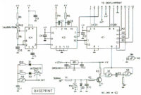
1Hz Clock Generator with Chip On Board (COB)
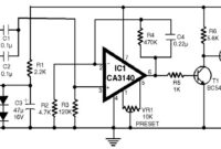
This is the 1Hz clock generator circuit with Chip On Board (COB). Commonly, the circuits to produce 1Hz clock for digital clock and counter circuits applications implement ICs in conjunction with a crystal and trimmer capacitors, […]
18 Watt Audio Amplifier with HA13118
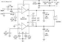
This is a 18 Watt audio amplifier circuit based on power IC HA13118. The supply voltage required for this circuit is 8 – 18V DC, at least 1 to 2 Amps. Maximum output power will only […]
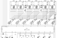
7 Segment LED Digital Clock with IC MM5314N
This is the circuit diagram of digital clock based on IC MM5314N. The clock display uses 6 pieces of 7 Segment LED with format HH:MM:SS. The power supply for this circuit already included, so you can […]
Digital Tachometer / RPM Meter
This is the circuit diagram of Digital Tachometer / Digital RPM Meter which can be used for cars or motorcycles with 2 and 4 stroke petrol engines with any number of cylinders and contact breaker or […]
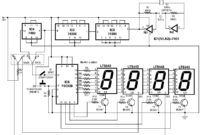
Electronic Stopwatch
The above simple circuit design can be utilized as an accurate stopwatch to count up to 100 seconds with a determination of 0.01 second or up to 1000 seconds with a determination of 0.1 second. This […]
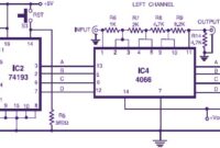
Stereo Digital Volume Control
Here is the circuit diagram of stereo digital volume control. This circuit could possibly be applied for upgrading your manual volume management within a stereo amplifier circuit. In this particular circuit, push-to-on switch S1 controls the […]
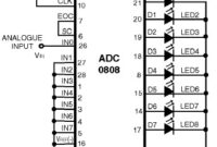
ADC0808 – Simple Analoque to Digital Converter
ADC0808 – Simple Analoque to Digital Converter This is a very simple analoque to digital converter circuit based on 8-bit analog-to-digital converter ADC0808. Typically analogue-to-digital converter (A/D Converter / ADC) requires interfacing through a microprocessor to […]
Arduino UNO
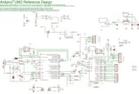
Here the Arduino UNO schematic diagram (click to enlarge): About Arduino UNO: The Arduino Uno is really a microcontroller board based on the ATmega328. It has 14 digital input/output pins (of which 6 may be employed […]
- 1
- 2

