
This is the digital fan speed control circuit design that can be utilize to control the speed of 220V fans using induction motor. The speed control is nonlinear, i.e. in steps. The current step number is displayed on a 7-segment display. Speed can be varied over a wide range because the circuit can alter the voltage applied to the fan motor from 130V to 230V RMS in a maximum of seven steps.
How the Digital Fan Speed Control Circuit Work
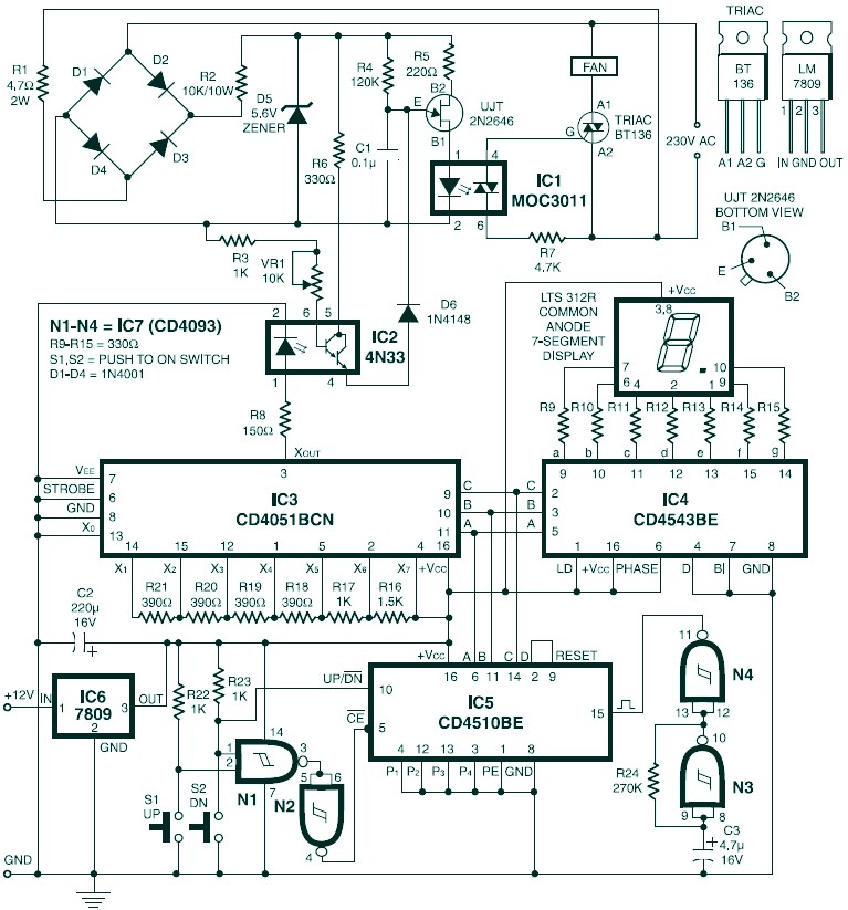
The triac used in the final stage is fired at different angles to get different voltage outputs by applying short-duration current pulses at its gate. For this purpose a UJT relaxation oscillator is used that outputs sawtooth waveform. This waveform is coupled to the gate of the triac through an optocoupler (MOC3011) that has a triac driver output stage.
The pedestal voltage control is used for varying the firing angle of the triac. The power supply for the relaxation oscillator is derived from the rectified mains via 10 Kohm, 10W series dropping/limiting resistor R2.
The pedestal voltage is derived from the non-filtered DC through optocoupler 4N33. The conductivity of the Darlington pair transistors inside this optocoupler is varied for getting the pedestal voltage. For this, the positive supply to the LED inside the optocoupler is connected via different values of resistors using a multiplexer (CD4051).
The value of resistance selected by the multiplexer depends upon the control input from BCD up-/down-counter CD4510 (IC5), which, in turn, controls forward biasing of the transistor inside optocoupler 4N33. The same BCD outputs from IC5 are also connected to the BCD-to-7-segment decoder to display the step number on a 7-segment display.
NAND gates N3 and N4 are configured as an astable multivibrator to produce rectangular clock pulses for IC5, while NAND gates N1 and N2 generate the active-low count enable (CE) input using either of push-to-on switches S1 or S2 for count up or count down operation, respectively, of the BCD counter.
Optocoupler 4N33 electrically isolates the high-voltage section and the digital section and thus prevents the user from shock hazard when using switches S1 and S2. BCD-to-7-segment decoder CD4543 is used for driving both common-cathode and common-anode 7-segment displays. If phase input pin 6 is ‘high’ the decoder works as a common-anode decoder, and if phase input pin 6 is “low” it acts as a common-cathode decoder.
Optocoupler 4N33 may still conduct slightly even when the display is zero, i.e. pin 13 (X0, at ground level) is switched to output pin 3. To avoid this problem, adjust preset VR1 as required using a plastic-handled screwdriver to get no output at zero reading in the display.
Digital Fan Speed Control Source: EFY Mag 11/2001


I need to make a TV Transmitter by mobile camera. But how do I this circuit diagram?