
This is the circuit diagram of Digital Tachometer / Digital RPM Meter which can be used for cars or motorcycles with 2 and 4 stroke petrol engines with any number of cylinders and contact breaker or electronic ignition systems. May be used as a general purpose revolution counter.
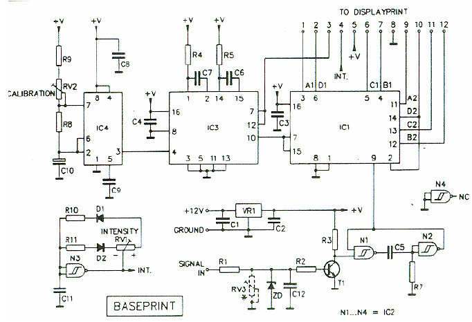
Digital Tachometer Mainboard Scheme:
Digital Tachometer Front Display Scheme:
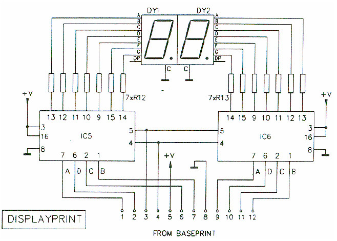
The digital RPM meter / tachometer comprises a motherboard and separate display board with a matching facia plate to provide a professional looking finish.
Digital Tachometer Specifications
- Range: 100 – 9900 revolutions/minute
- 2 digit display showing hundreds and Thousands of rPM’s (x100)
- Easy calibration
- Suitable for 2 and 4 stroke with Any number of cylinders
- Suitable for contact breaker or electronic ignition systems
- Contact breaker debounce circuit
- Resolution: 100 RPM
- Adjustable brightness
- Power supply: 10 – 15VDC / 200mA
The kit for this circuit is available, you may purchase the kit at quasarelectronics.co.uk.
Download the manual book about this circuit include the part list and how to assemble this circuit:


