
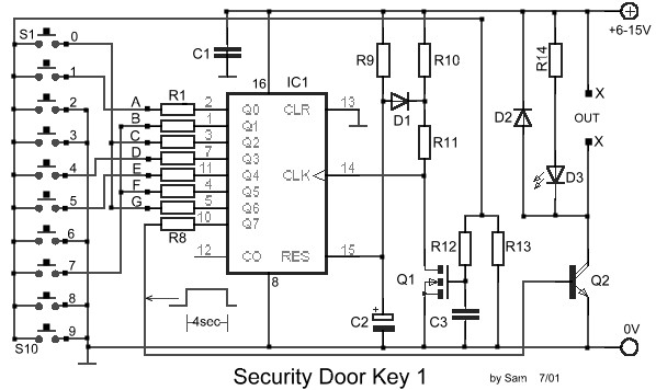
This is the circuit diagram electronic door lock security key system. It means that this security system circuit is the combination of pressed key itself (not the mechanical). The output can be connected to drive the relay to open the door (usually using motor).
It is a quite simple circuit of electronic door lock with security code of 7 digits. Attention must be paid in time we pressed the keys forming the code and there is no delay. With the right keys and if the correct code will activate the output Q7 for about 4 seconds, driving the transistor Q2, which can be used to activate a relay and opening the door, or can be used for any other circuit. The LED used for visual indication of activation. The seven-digit combination code of the above circuit is: 1704570, but can be changed the combination of secure key by exchange the connections between the outputs of the counter IC1 and switches.
Electronic Door Lock Security Key Components List
| R1,R2,R3,R4,R5,R6,R7 = 4.7Kohm R8 = 15Kohm R9 = 1Mohm R10,R13 = 10Kohm R11 = 100ohm R12 = 220Kohm R14 = 1.2Kohm |
C1,C3 = 100nF/100V C2 = 4.7uF/25V Q1 = BS170 Q2 = BD679 IC1 = 4022 D1-2 = 1N4148 D3 = RED LED 3mm S1-10 = Push button or keyboard |


This circuit is useful for me & this will be very surprising to me to make your circuit myself.I would be very thankful to you to upload the circuit on website.
send me the components of the circuit.Thanks
I’m sorry i forgot to give the part list. It should be clear now.. 🙂
please give me Q2 value.
need the components.plz send me
i am also need components plz send me thank you
pls send me the components of the circuit.Thanks