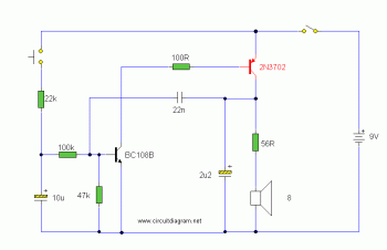
This is Electronic Siren circuit diagram which use standard discrete components. The sound produced imitates the rise and fall of an American police siren. When first switched on the 10u capacitors is discharged and both transistors are off. When the push button switch is pressed to 10u capacitor will charge via the 22k resistor. This voltage is applied to the base of the BC108B which will turn on slowly. When the switch is released the capacitor will discharge via the 100k and 47k base resistors and the transistor will slowly turn off. The change in voltage alters the frequency of the siren.
The siren sound generated from the oscillation process. Oscillator action is as follows:
As the BC108B transistor switches on its collector voltage falls and so the 2N3702 transistor is switched on. The process is very fast ( less than 1us). The 22n capacitor will charge very fast as well. As this capacitor is wired between the collector of the 2N3702 and the base of the BC108B, it soon reaches almost full supply voltage. The charging current for the capacitor is then much reduced and the collector emitter voltage of the 2N3072 is therefore increased; the collector potential will fall. This change in voltage is passed through the 22n capacitor to the base of the BC108B causing it to come out of saturation slightly. As this happens its collector voltage will rise and turn off the 2N3072 transistor more. This continues until both transistors are off. The 22n capacitor will then discharge via the 100k, 22k resistor, the closed push button switch, 9V battery, the speaker and 56 ohm resistor. The discharge time takes around 5-6msec. As soon as the 22n capacitor is discharged, the BC108B transistor will switch on again and the cycle repeats. The difference in voltage at the collector of the BC108B (caused by the charging 10u capacitor) causes the tone of the siren to change. As the 10u capacitor is charged, the tone of the siren will rise, and as it is discharged, it will fall. A 64 ohm loudspeaker may be used in place of the 8 ohm and 56 resistor, and the values of the electronic components may be changed to generate different sound effects of the siren.
Current drain is fairly high in this circuit so a suitable power supply is needed. The duration the tone takes to rise and fall is determined by the 10u and 22k resistor. These values may be changed for different effects.


