
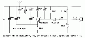
This is a mini fm transmitter circuit. I think this is the simplest one. Simple, easy and of course… inexpensive… The supply voltage is between 1.1 – 3 Volts with power consumption is 1.8 mA at 1.5 Volts. This circuit should be able to cover? 30 – 50 meters of range max. at 1.5 Volts.
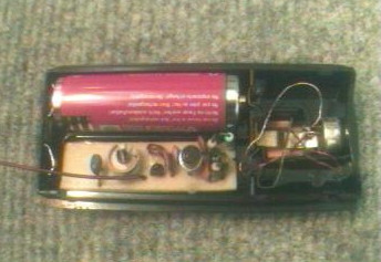
Main advantage of this circuit is that power supply is a 1.5Volts cell (any size) which makes it possible to fix PCB and the battery into very tight places. Transmitter even runs with standard NiCd rechargeable cells, for example a 750mAh AA size battery runs it about 500 hours (while it drags 1.4mA at 1.24V) which equals to 20 days. This way circuit especially valuable in amateur spy operations 🙂
Transistor is not a critical part of the circuit, but selecting a high frequency / low noise one contributes the sound quality and range of the transmitter. PN2222A, 2N2222A, BFxxx series, BC109B, C, and even well known BC238 runs perfect. Key to a well functioning, low consumption circuit is to use a high hFE / low Ceb (internal junction capacity) transistor.
Not all of the condenser microphones are the same in electrical characteristics, so after operating the circuit, use a 10K variable resistance instead of the 5.6K, which supplies current to the internal amplifier of microphone, and adjust it to an optimum point where sound is best in amplitude and quality. Then note the value of the variable resistor and replace it with a fixed one.
The critical part is the inductance L which should be handmade. Get an enamelled copper wire of 0.5mm (AWG24) and round two loose loops having a diameter of 4-5mm. Wire size may vary as well. Rest of the work is much dependent on your level of knowledge and experience on inductances: Have an FM radio near the circuit and set frequency where is no reception. Apply power to the circuit and put a iron rod into the inductance loops to chance it”s value. When you find the right point, adjust inductance”s looseness and, if required, number of turns. Once it”s OK, you may use trimmer capacitor to make further frequency adjustments. You may get help of a experienced person on this point. Do not forget to fix inductance by pouring some glue onto it against external forces. If the reception on the radio lost in a few meters range, than it”s probably caused by a wrong coil adjustment and you are in fact listening to a harmonic of the transmitter instead of the centre frequency. Place radio far away from the circuit and re-adjust. An oscilloscope would make it easier, if you know how to use it in this case.
Every part should fit on the following PCB easily. Pay attention to the transistor”s leads which should be connected right. Also try to connect trimmer capacitor”s moving part to the + side, which may help unwanted frequency shift while adjusting. PCB drawing should be printed at 300DPI, here is a TIFF file already set.
Mini FM Transmitter PCB Layout:

Technical data:
Supply voltage : 1.1 - 3 Volts
Power consumption : 1.8 mA at 1.5 Volts
Range : 30 meters max. at 1.5 Volts

be it more clrar