
The following is LED Flasher circuit which use 2 transistors for LED switching. The circuit works similar to flip-flop operation.
Components List:
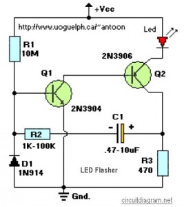
| R1 = 10M ohm R2 = 1K – 100K ohm R3 = 470 ohm C1 = 0.47uF – 10uF/25V |
D1 = 1N914 Q1 = 2N3904 Q2 = 2N3906 Led = High Brightness Red LED |
This circuit will flash a bright or high-brightness red LED (5000+ mcd). Great for fake car alarm or other awareness getting equipment. Component values aren’t significant, attempt anything else first from the junkbox.Obviously, the 470 ohm resistor (R3) determines the LED’s brightness and limits the current flow to around 20mA. R3 value of 390 ohm can also be implemented as a save value.
If you determine to go with a green or yellow led, which take extra current, you might wish to change the 470 ohm with an proper value. Flash rate is determined by R2 and C1 and it is approximately three time constants (3*R2*C1). R1 provides bias to Q1 which should be low enough not to saturate Q2 with the capacitor disconnected. When the circuit does not oscillate, R1 may be too low or R2 too high. D1 allows for higher duty cycle operation and limits the feedback at the base of Q1 to -0.7 volts. D1 might be ommited for low supply power like 6 – 9V and low duy cycle operation.
LED Flasher 2-Transistors, circuit design by Tony Van Roon


