
This is the positive voltage regulator circuit with PNP Boost transistor:
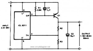
The IC8211 presents the voltage reference and regulator amplifier, while Q1 will be the series pass transistor. R1 defines the output current of the IC8211, while C1 and C2 present loop stability and as well act to suppress feedthrough of input transients to the output supply. R2 and R3 define the output voltage as follows:
![]()
Furthermore, the values of R2 and R3 are preferred to produce a little volume of standing current in Q1, which provides extra stability margin on the circuit.Where accurate setting of the output voltage is needed, either R2 or R3 could be designed adjustable. If R2 is designed become adjustable,then the output voltage will vary linearly with the shaft angle; nevertheless, if the potentiometer wiper was to open the circuit, the output voltage would rise. Normally, for that reason, it’s more beneficial to provide R3 adjustable, because this will give fail-safe operation.


