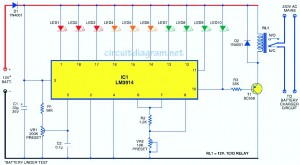
Here the circuit diagram of simple and easy made battery level indicator. In general, in mobile phones, the battery levels is displayed in dot or bar style. This helps you to effortlessly acknowledge the battery level. On this page we provide a circuit that helps you to recognize the battery level of a instrument from the quantity of LEDs which are glowing. It applies 10 LEDs in all. So if 3 LEDs light, it signifies battery power of 30 percent. Different from in mobile phones in which the battery level indicator functionality is integrated with other functions, in this circuit just one single comparator IC (LM3914) does it all.
The LM3914 utilizes 10 comparators, that are internally built in the voltage divider network according to the current division rule. So it splits the battery level into 10 portions.
The circuit gets the power source for its operation from the battery of the instrument itself. It utilizes 10 LEDs connected in a 10-dot mode. Applying various coloured LEDs helps make it simplier and easier to determine the voltage level on the basis of the calibration made. Red LEDs (LED1 through LED3) show battery power of lower than 40 percent. Orange LEDs (LED4 through LED6) show battery power of 40 to lower than 70 percent and green LEDs (LED7 through LED10) show battery power of 70 to below 100 percent. The brightness of the LEDs could be fine-tuned by altering the value of variable resistor VR2 in between pins 6 and 7.
Diode D1 prevents the circuit from reverse-polarity battery connection. The tenth LED glows only if the battery power is full, i.e., the battery is totally charged. When the battery is fully charged, relay driver transistor T1 performs to energise relay RL1. This stops the charging by way of normally open (N/O) contacts of relay RL1.
For calibration, connect 15V adjustable, regulated power source and at first set it at 3V. Gradually alter VR1 until eventually LED1 glows. Now, enhance the input voltage to 15V in steps of 1.2V right up until the corresponding LED (LED2 through LED10) illuminates.
Now the circuit is prepared to display any voltage value with respect to the maximal voltage. Since the quantity of LEDs is 10, we are able to simply give consideration to a single LED for 10 percent of the maximal voltage.
Connect the voltage from any battery to get tested at the input probes of the circuit. By looking at the total number of LEDs glowing you are able to very easily know the level of your battery. Suppose 5 LEDs are glowing. Within this case, the battery power is 50 to 59 percent of its maximal value.
Build this simpe battery level indicator circuit on a general purpose PCB. Calibrate it and after that, enclose inside a case. Make 10 holes for the LED, a hole for battery input and 2 holes for variable resistor if necessary.


What do you do change to use this circut with a 5v battery
Good information.. 🙂