
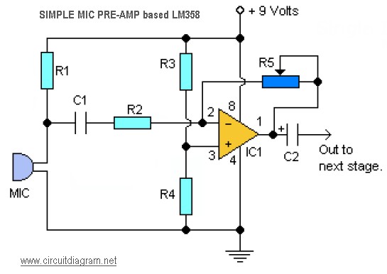
Here the simple mic pre-amp circuit design based on single IC LM358. The circuit is very simple, inexpensive and easy to built. This mic pre-amplifier circuit operated with 9V DC voltage, you may use 9V battery for this circuit.
Component Parts List:
R1, R3, R4 = 10K
R2 = 1K
R5 = 100K-1M Potensiometer
C1 = 0.1uF
C2 = 4.7uF/16V
IC1 = LM358 dual op-amp single supply
Mic = Electret Microphone
Notes:
- Use R5 to adjust the gain of op-amp LM358.
- The LM358 has dual op-amp module, you may build stereo audio pre-amp using single LM358. These devices consist of two independent, high-gain frequency-compensated operational amplifiers designed to operate from a single supply over a wide range of voltages.
Download PDF document of LM358 datasheet from below link:
The simple mic pre-Amp based LM358 circuit designed by Tony van Roon


what will be better lm358 or lm386 as i want the input from the microphone to be given to micro-controller
I rebuilt my circuit this morning and got better results. The oscillations are now proper. I do still have a DC offset, but I guess something like a speaker will only catch the alternating signals any way (I ditched the resistor I had added to the output cap).
I tried building this for my guitar as a test. My output from C2 before I hooked the guitar up was floating around 3.7V, so I grounded it with a 100k resistor (high-pass filter). Is this normal, or did I hook something up wrong? Also, I only seem to be getting voltages above the output, isn’t the point of the voltage divider on pin 3 to allow signals to oscillate around 2.5V up AND down?
thanks for help
hello
i want amplify the weak audio signal. in your point of view which of this op-amp suitable:
lm358 vs 741?
Q1: Yes, this work with 5V supply. LM358 has a wide rang voltage supply of 3V to 32V. You may try to lower the R1 value.
Q2: The output will be to the mixer circuit, echo chamber, or directly to the tone control circuit.
Hi,
Q1. You have a power supply of 9V in the circuit. Will this circuit work if I have a 5 V supply? If it can, then obviously the values of the capacitors and the resistors would change. Are there any rules or equations that I may need to calculate the values of components if I have a 5 V supply?
Q2. Where does the output of the system go to?