
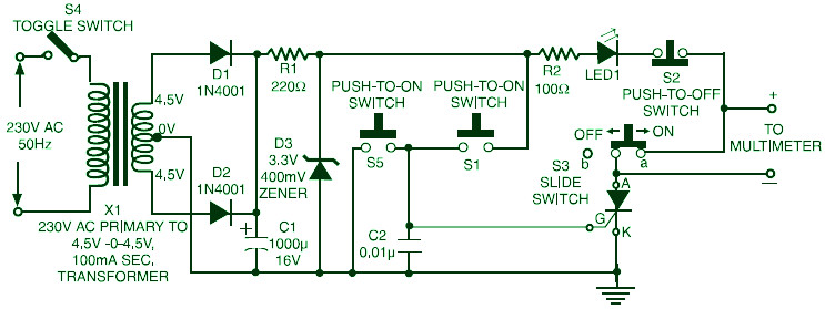
This is the circuit diagram of TRIAC, SCR and Transistor tester. This is a very simple circuit which can be used for testing of SCRs as well as triacs. The circuit could even be used for checking of PNP and NPN transistors.
The circuit works on 3V DC, derived using a zener diode in conjunction with a step-down transformer and rectifier arrangement, as shown in the figure. Alternatively, one may power the circuit using two pencil cells.
For testing an SCR, insert it in the socket with terminals inserted in proper slots. Slide switch S3 to “on” position (towards “a”) and press switch S1 momentarily. The LED would glow and keep glowing until switch S2 is pressed or mains supply to step-down transformer is interrupted for a short duration using switch S4. This would indicate that the SCR under test is serviceable.
With switch S3 in “off” position (towards “b”), you may connect a milliammeter or a multimeter to monitor the current flowing through the SCR. If the SCR is “no good,” the LED would never glow. If the SCR is faulty (leaky), the LED would glow by itself. In other words, if the LED glows only on pressing switch S1 momentarily and goes off on pressing switch S2, the SCR is good.
For testing a triac, initially connect its MT1 terminal to point A (positive), MT2 to point K (negative), and its gate to point G. Now, on pressing switch S1 momentarily, the LED would glow. On pressing switch S2 momentarily, the LED would go off. Next, on pressing switch S5, the LED will not glow.
Now reverse connections of MT1 and MT2, i.e. connect MT1 to the negative and MT2 to the positive side. For a good working triac, S2 would not initiate conduction in the triac and the LED would remain off. On the other hand, momentary depression of S5 would initiate conduction of the triac and LED1 would glow.
The indication of a leaky triac is similar to that of an SCR. If, during both the above-mentioned tests, the LED lights up, only then the triac is good.
Before connecting any SCR/triac in the circuit, please check its anode/MT1’s connection with the case. (Note: A triac is actually two SCRs connected back to back. The first accepts positive pulse for conduction while the second accepts negative pulse for conduction.)
Transistor Tester Usage
You can also check transistors with this circuit by introducing a resistor (about 1 kilo-ohm) between the junction of switches S1 and S5 and point G. The collector of NPN or emitter of PNP transistor is to be connected to positive (point A), while emitter of an NPN and collector of a PNP transistor is to be connected to negative (point K). The base in both cases is to be connected to point G.
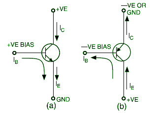
Above figure indicates the conventional current direction and forward biasing condition for PNP and NPN transistors. If the transistor under test is of NPN type, on pressing S1, the LED glows, and on releasing or lifting the finger, it goes off, indicating that the transistor is good. For PNP transistor, the LED glows on pressing switch S5 and goes off when it is released. This indicates that the transistor under test is good. A leaky or short-circuited SCR or transistor would be indicated by a permanent glow of the LED by itself, i.e. without pressing switch S1 or S5.
Triac, SCR, transistor tester circuit come from EFYmag 2001


