
Here is the circuit diagram of ultrasonic sensor switch. There are many methods of wireless switching such as by using infrared, AM/FM signal, bluetooth, etc. This is an alternate wireless switching by using ultrasonic sensor. The distance of switching range should be more than 10 meters. This circuit produces and transmits ultrasonic sound of frequency between 40 and 50 kHz. Similar to the other remote control systems, this circuit comprises of a mini transmitter and a receiver circuit. Transmitter generates ultrasonic sound and the receiver senses ultrasonic sound from the transmitter and switches on a relay.
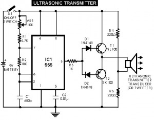
Ultrasonic Transmitter Parts List:
IC1 = NE555 timer IC
VR1 = 10k variable resistor
R1 = 4.7k resistor
R2 = 18k potentiometer
R3 = 1k resistor
R4, R5 = 220 ohm resistor
C1 = 680 picofarad capacitor
C2 = 0.01uf capacitor
D1, D2 = 1N4148 Diode
T1 = SL100 NPN transistor
T2 = SK100 PNP transistor
S1 = SPST momentary contact switch
XMTR = ultrasonic transmitter 40-50khz
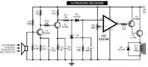
Ultrasonic Receiver Parts List:
RCVR = Ultrasonic Receiver 40-50khz
RL1 = 6volt 200ohm resistor
IC2 = CA3140
VR2 = 250k Variable Resistor
R6 = 390k Resistor
R7 = 470k Resistor
R8, R12 = 15k Resistor
R9 = 12k
R10, R13 = 10k
R11 = 4.7k
R14 = 100k Resistor
R15 = 33 ohm Resistor
C3 = 0.22uf ceramic capacitor
C4 = 0.1uf ceramic capacitor
C5 = 560n ceramic capacitor
T3,T4 = BC548 NPN Transistor
T5 = BC558 PNP Transistor
T6 = SL100 NPN Transistor
D3,D4,D5 = 1N4148 Diode
The ultrasonic transmitter uses a 555 based astable multivibrator. It oscillates at a frequency of 40-50 kHz. An ultrasonic transmitter transducer is used here to transmit ultrasonic sound very effectively. The transmitter is powered from a 9-volt PP3 single cell. The ultrasonic receiver circuit uses an ultrasonic receiver transducer to sense ultrasonic signals. It also uses a two-stage amplifier, a rectifier stage, and an operational amplifier in inverting mode. Output of op-amp is connected to a relay through a complimentary relay driver stage. A 9-volt battery eliminator can be used for receiver circuit, if required. When switch S1 of transmitter is pressed, it generates ultrasonic sound. The sound is received by ultrasonic receiver transducer. It converts it to electrical variations of the same frequency. These signals are amplified by transistors T3 and T4. The amplified signals are then rectified and filtered. The filtered DC voltage is given to inverting pin of op-amp IC2. The non- inverting pin of IC2 is connected to a variable DC voltage via preset VR2 which determines the threshold value of ultrasonic signal received by receiver for operation of relay RL1. The inverted output of IC2 is used to bias transistor T5. When transistor T5 conducts, it supplies base bias to transistor T6. When transistor T6 conducts, it actuates the relay. The relay can be used to control any electrical or electronic equipment.
Circuit notes:
- Frequency of ultrasonic sound generated can be varied from 40 to 50 kHz range by adjusting VR1. Adjust it for maximum performance.
- Ultrasonic sounds are highly directional. So when you are operating the switch the ultrasonic transmitter transducer of transmitter should be placed towards ultrasonic receiver transducer of receiver circuit for proper functioning.
- Use a 9-volt PP3 battery for transmitter. The receiver can be powered from a battery eliminator and is always kept in switched on position.
- For latch facility use a DPDT relay if you want to switch on and switch off the load. A flip-flop can be inserted between IC2 and relay. If you want only an ?ON-time delay? use a 555 only at output of IC2. The relay will be energised for the required period determined by the timing components of 555 monostable multivibrator.
- Ultrasonic waves are emitted by many natural sources. Therefore, sometimes, the circuit might get falsely triggered, espically when a flip-flop is used with the circuit, and there is no remedy for that
Please visit this page for more explanation.


please sent me layout diagram of ultrasonic switch