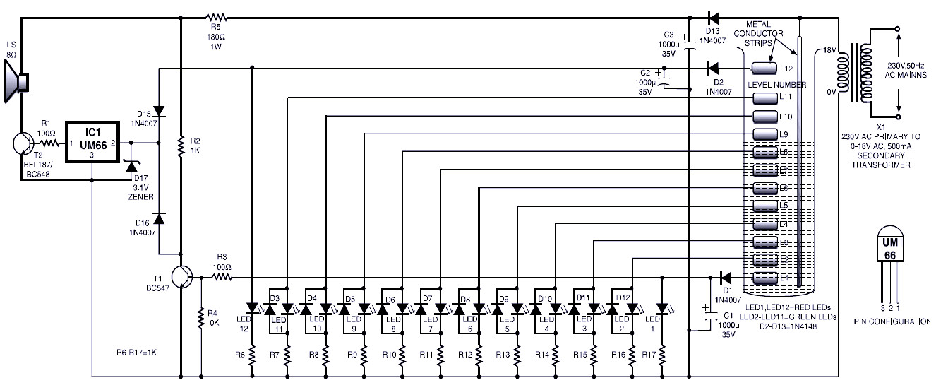
In this circuit, the diodes D1, D2 and D13 act as a half-wave rectifier. Rectified output is filtered using a capacitor C1 through C3 respectively.
Initially, when the water level is below the L1 strip, supplying electrical oscillation frequency is not transferred to the diode D1. Thus the low output and LED1 does not light. Also, because the base voltage of the transistor T1 is low, it is in a state of cut-off and the collector voltage is high, which enables to produce melody IC1 (UM66) and the alarm is sounded.
When the water is just touching the L1 level detector strip, the oscillation frequency of the supply transferred to the diode D1. This straightening supply voltage and positive DC voltage developing capacitor C1, which is lit LED1. At the same time the base voltage of the transistor T1 becomes high, which makes forward bias and collector voltage falls to near ground potential. Disabling IC1 (UM66) and the alarm is inhibited.


Do not implement this circuit, it is “not safe”, not reliable, not efficient, and not practical to implement. There are many other simpler circuits that can serve the purpose.