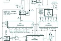
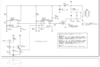
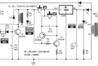
This is the digital fan speed control circuit design that can be utilize to control the speed of 220V fans using induction motor. The speed control is nonlinear, i.e. in steps. The current step number is […]
Category: Motor Related
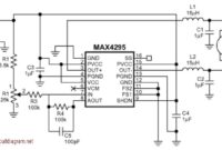
Motor Speed Control with MAX4295
This is a motor speed controller circuit diagram built based MAX4295 from Maxim. By using this circuit, you will be able to control the speed of motor movement. Resistor R1 biases the potentiometer to match the […]
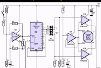
Stepper Motor Controller Using TDA2030
There are many version of stepper motor type, also the many version of stepper motor controller design. This circuit is a general-purpose stepper motor controller that use IC TDA2030 as the driver. This circuit can be […]
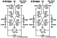
6 Transistor Tilden’s H-Bridge
This diagram is certainly the 6 transistor Tilden H-bridge circuit; while not as old as the original “basic H-bridge,” this goes “way back,” and will be the basis for a lot of BEAM driver circuits. Bruce […]
DC Motor Controller using Transistor TIP31
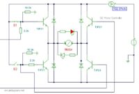
This is a DC motor controller circuit, built using transistor TIP31 based on H-Bridge concept. The switch S1 and S2 are normally open , push to close, press button switches. The LED function is to indicate […]
Bipolar Stepper Motor Driver
This bipolar stepper motor driver circuit will drive a bipolar stepper motor using externally supplied 5V levels for stepping and direction. These usually come from software running in a computer or from a microcontroller unit. The […]
PWM DC Motor Controller with MOSFET
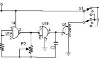
This is the simple and low cost pulse width modulation – PWM DC motor controller using a MOSFET. This kind connection for DC motor control is to prevent heat and minimize the power consumption. It controls […]
Unipolar Stepper Motor Driver
This is the circuit design of unipolar stepper motor driver to control unipolar stepper motors with 5, 6 or 8 wires. It uses four MOSFET IRFZ44. This circuit can be operated in free-standing or PC-controlled mode.
DC Motor Speed Controller
This is the schematic diagram of DC motor speed controller circuit. The circuit applies two oscillators/timers which are connected as a Pulse Width Modulator (PWM). The timer chip which applied in this circuit will be an […]
Electronic Motor Starter
The above diagram is the schematic diagram of an electronic motor starter circuit. This motor starter protects singlephase motors against voltage fluctuations and overloading. Its salient function is a soft on/off electronic switch for simple operation. […]

