
This is the inverter circuit which capable to convert 12V DC to 220V AC dan handle about 50 Watts small electronic appliances. With this circuit, you can use a 12V accumulator / lead acid battery to operate some of your electronic appliances which not exceed 50W of total power consumption.

Components List:
| R1=10Mohms R2=100ohms R3=1.2Kohms R4=560Kohms R5-6=2.2Kohms R7-8=56 ohms 5W CX=22pF trimmed capacitor C1-2=22pF ceramic C3=8.2nF 100V MKT |
C4=10uF 16V C5=47uF 16V C6=470nF 400V D1=5V6 0.4W D2-3=47V 1W Q1-2=BS170 Q3-4=BD139 Q5-6=BD249 IC1=4060 |
IC2=4013 IC3=4047 CR1=3.2768 MHZ crystal T1=220Vac/2X10V 2X2.2A F1=5A Fuse F2=0.25A Fuse L1=1H smoothing choke |
The above inverter circuit converts 12VDC to 220VAC with power of about 50W. To circuit consists of the oscillator around the IC1, a divider IC2, an unstable polydoniti IC3, which gives the output of a symmetrical rectangular signal frequency 50HZ, followed by a buffer stage with Fet Q1-2, the driver stage and Q3-4 the power stage Q4-5, power transistors Q5-6, should be placed on a heatsink .. diodes Zener D2-3 protect the power transistors from voltage spikes produced by the transformer T1.
The transformer T1 are a simple power transformer with a medium shot, which is connected to the contacts of CO1. To use the wish, o T1, is placed upside down, with the secondary winding be used as primary, with the receiving means being connected to the positive battery voltage is 12V and the two other contacts are connected to the emitters of Q5-6, the connected to earth potential alternately, depending on the rate set by the outputs 10 and 11 of IC3. In this manner while flowing in the primary alternating current generated in the secondary alternating rectangular voltage 220V.
Using crystal oscillator ensures very good reference frequency 50HZ, and use a common crystal (CR1). For greater accuracy in parallel with C1, a variable capacitor CCH ensuring the adjustment of the frequency, in order to obtain the point P1 frequency 204.8 KIZ. It is evident that the output voltage at no-load is higher than the voltage under load. Also, the output voltage depends on the battery voltage. Thus for 14V battery voltage, the output voltage is increased by 10%, compared with the battery output voltage to 12V. If the converter works in load power 40 until 60W, then it can be used 2CH9V transformer. Various output values ??for battery voltage 12V transformer and 2CH10V.
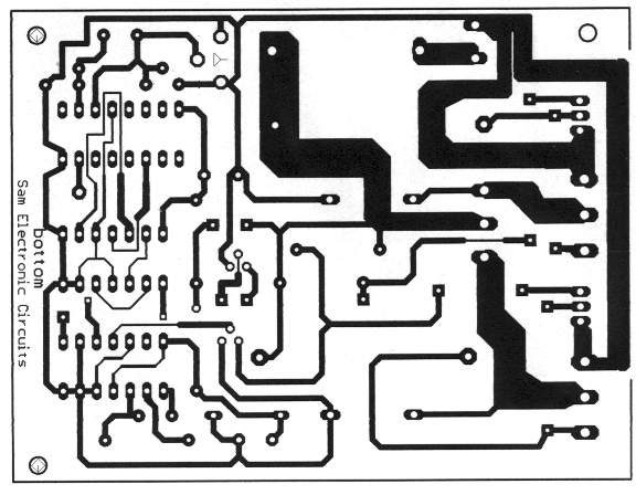
50W Inverter 12VDC to 220VAC PCB Design:
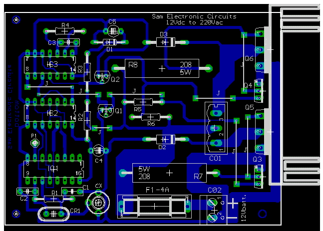
50W Inverter 12VDC to 220VAC Component Placement:


can i use 12 0 12secondary 230volt primary 2amp transformer in this circuit
Can you please also describe the battery configuration with this. It would be helpful to beginers.
plz send me the ckt diagram of 3000w inverter and its component list plz…..
sir
senpower convertor is swich off or power off 220 .bycing volt not showing which icc vol is required for opening .can u show sever manula book?
hello sir,
i want to make a generator using battery (replacing diesel) and i want to know that how i can convert 12 volt to 220ac , 500 w.
Ineed from you 12,24 and 48 vdc to 220ac inverter circuit diagram so please send me.