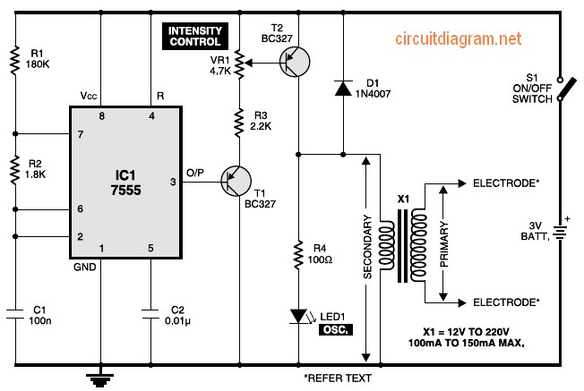
Figure 1 exhibits the circuit with the muscular stimulator. IC 7555 is actually wired just as one astable multivibrator to build about 80Hz pulses. The particular output involving IC1 is fed to be able to transistor T1, whose emitter is actually further connected to the starting of transistor T2 via R3 as well as VR1. The enthusiast of transistor T2 is connected to one end of the secondary turning of transformer X1. The opposite end on the secondary winding from the transformer is connected to ground.

