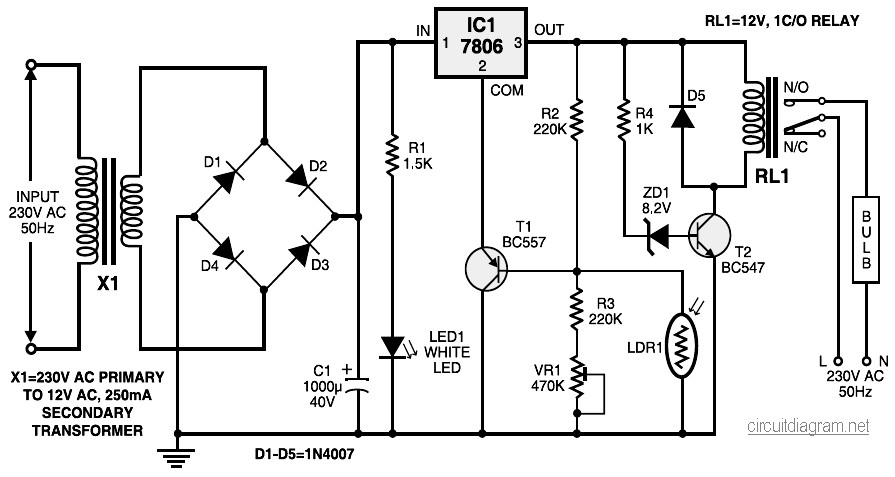
Automatic light controller circuit.
During night time, when no light falls on LDR1, it offers a high resistance at the base junction of transistor T1. So the bias is greatly reduced and T1 doesn”t conduct. Effectively, this removes the common terminal of IC1 from ground and it directs the full input DC to the output. Transistor T2 conducts and the relay energises to light up the bulb as mains connection completes through the relay contacts.

