
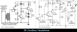
This is the schematic diagram of Infrared (IR) cordless headphone. Maybe it also can be called “wireless headphone”, but it use infrared as sound signal carrier. It use a pair of circuit diagrams that are IR transmitter and IR reveiver. Using this low-cost project one can reproduce audio from TV or other electronic devices without disturbing others. It does not use any wire connection between TV and headphones. In place of a pair of wires, it uses invisible infrared light to transmit audio signals from TV to headphones. Without using any lens, a range of up to 6 metres is possible. Range can be extended by using lenses and reflectors with IR sensors comprising transmitters and receivers.
IR transmitter uses two-stage transistor amplifier to drive two series-connected IR LEDs. An audio output transformer is used (in reverse) to couple audio output from TV to the IR transmitter. Transistors T1 and T2 amplify the audio signals received from TV through the audio transformer. Low impedance output windings (lower gauge or thicker wires) are used for connection to TV side while high-impedance windings are connected to IR transmitter. This IR transmitter can be powered from a 9-volt mains adapter or battery. Red LED1 in transmitter circuit functions as a zener diode (0.65V) as well as supply-on indicator.
IR receiver uses 3-stage transistor amplifier. The first two transistors (T4 and T5) form audio signal amplifier while the third transistor T6 is used to drive a headphone. Adjust potensiometer VR2 for maximum clarity.
Direct photo-transistor towards IR LEDs of transmitter for maximum range. A 9-volt battery can be used with receiver for portable operation.
Good luck…


