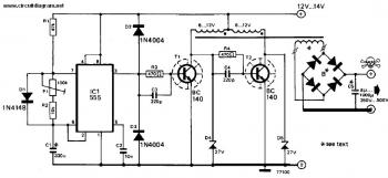
This inverter 12V DC to 240V DC can be used to power electric razors, stroboscopes and flash tubes, and small fluorescent lamps from a 12 volt car battery. In contrast to the usual feedback oscillator type of inverter, the oscillator of this inverter is separate from the output stage, which allows easy adjustment of the oscillator frequency to suit different applications.
The oscillator circuit consists of a 555 timer connected as an astable multivibrator. The inclusion of D1 ensures that the duty-cycle of the squarewave output is maintained at about 50%. The output of the 555 drives the base of T1 which switches current through one half of the primary of the transformer. T2 is driven from the collector of Tl and thus switches current through the other half of the transformer winding on opposite half cycles of the drive waveform. Zener diodes D4 and D5 protect Tl and T2 from any high-voltage spikes generated by the transformer.
The voltage applied to the transformer primary is stepped up and the required high output voltage appears across the secondary winding. Depending on the application the secondary voltage may or may not be rectified.
Download the full explanation about this inverter 12V DC to 240V DC circuit:


sir
I request to you
please send tested all 10 to 5000w invertor circuit with video, component details,construction report in pdf
(shubhamkalaskar13@gmail.com)
You can buy our latest 48v Converter or other high efficiency components from our website at Dctodcpower.com. We mainly provide popular products with high quality at home and abroad and create competitive advantages for our customers over their own competition. For more details visit our website.
Plse I need a help with how to build a inverter
5V Regulated Solar Cell Power Supply
5V Regulated Solar Cell Power Supply
100 Watt Inverter 12VDC to 220VAC with Mosfet
100 Watt Inverter 12VDC to 220VAC with Mosfet
This is another 100 watt inverter circuit diagram. Built based on IC CD4047 and Mosfet IRF540, this inverter have ability to supply electronic device -which require 220VAC- up to 100w from 2-3A transformer from 12V lead acid battery. In the circuit diagram we can observe that 12V battery …
50W Inverter 12VDC to 220VAC
50W Inverter 12VDC to 220VAC
This is the inverter circuit which capable to convert 12V DC to 220V AC dan handle about 50 Watts small electronic appliances. With this circuit, you can use a 12V accumulator / lead acid battery to operate some of your electronic appliances which not exceed 50W of total …
25W Low Power Inverter
25W Low Power Inverter
This is 25W low power inverter which contain of only 9 parts and turn 10VDC – 16VDC into 115V / 60Hz square wave power. This circuit has capability to operate AC equipment up to 25W. The first section of the 555 timer is wires as an astable oscillator …
Power Inverter 100W, 12V DC to 220V AC
Power Inverter 100W, 12V DC to 220V AC
Here is 100 Watt Inverter 12V DC to 220V AC schematic diagram. This circuit designed using the combination of main components IC CD4047, Transistor TIP122 and 2N3055. Circuit Notes: A 12 V car battery can be used as the 12V source. Use the POT R1 to set the …
5V Regulated Solar Cell Power Supply
5V Regulated Solar Cell Power Supply
Powered with solar panel, the circuit will give you 5V pure regulated DC voltage. The circuit is made up of an oscillator transistor as well as a regulator transistor. The solar panel charges the battery when sunlight is bright enough to generate a voltage above 1.9v. A diode …
Category: Inverter Power Electronics Tags: 12v inverter circuit diagram, 12v to 230v inverter circuit, 12v to 240v inverter, 12v to 240v inverter circuit diagram, car battery inverter supply 240v, circuit diagram of inverter, Inverter, inverter circuit diagram, inverter circuit diagram 12v, power inverter, power inverter dc to ac 12 to240circuit diagram, power inverter dc to ac 12v to 240v circuit diagram