
This is the LED flashing circuit, since the shape used in this circuit was hearth shape, then we call it LED flashing heart circuit. The circuit is quite simple, low cost, easy to built. Alternatively, you could be create another shape, not just heart shape.
Schematic diagram:
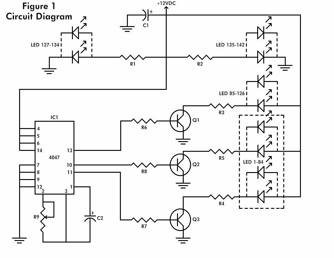
Component list:
| Resistors | ||
| R1, R2 | – | 470 ohm, 1/2-watt |
| R3-R5 | – | 100 ohm, 3-watt |
| R6-R8 | – | 1000 ohm, 1.4-watt |
| R9 | – | 5000 ohm potentiometer |
| Capacitors | ||
| C1, C2 | – | 100uF, 16 volts, electrolytic radial |
| Semiconductors | ||
| IC1 | – | 4047, low power monostable/astable multivibrator |
| Q1-Q3 | – | 2n3643 NPN transistor or equivalent |
| Diodes | ||
| LED1-LED84 | – | yellow light-emitting diode |
| LED85-LED126 | – | red light-emitting diode |
| LED127-LED142 | – | green light-emitting diode |
| Other components | ||
| PS1 | – | 12VDC @ 500mA wall transformer |
| Miscellaneous: Jumper wire, solder, printed circuit board, | ||
| drill and bits,14 pin I.C. socket, and a frame or case. | ||
PCB layout:

Component placement:

Once power has been applied to the circuit, the Red LEDs should all be flashing on and off together. The Yellow LEDs should be flashing on and off, but only every other Yellow LED should be on at one time. The Green LEDs will stay on at all times. The flash rate can be adjusted by turning R9. Connections for a fixed value resistor for R9 are provided on the board layout if preferred.To dress up the project, a favorite photograph can be placed in the heart, and a frame can be made to fit the circuit board.
Complete explanation, please visit this page


Hello! I know it’s a bit late but I found this project and wanted to give it a try.
I have already built it up and it works… but not properly…. The green leds stay on, the red ones blink but only some of the yellow blink alternatively, I mean, half of the yellow leds light up but the others don’t. All the connectios are well soldered because I’ve double-checked it. So, for those who wander (tom and jajaja), it works and it is worth the effort and the money. I had fun making it and although is not working I’m proud of this project. I’m sure that looking at the schematics at the end I will find a solution, but if anyone could help me it would be amazing!
So,if somenone can read this and want an image or a video just send a message!
Hope I can get an anwser!
Alexis (Spain)
hola puedo imprimir directamente el circuito de la figura 2 y plancharlo en la baquelita. o nececito el efecto de espejo
or course it will work because the circuit already tested. the negative pin of LEDs should be the pin which connected to the ground.. 🙂
will this actually work?please post something here if somebody tried and tested this circuit
im doing this now how will i find where is the positive and negative in the leds??
how will it blink, frequency is not present for clocking?
materials are not complete here in dumaguete…
I’m from turkey…
Yellow LED (+) (-) from??
good luck 😉
Anyone got this working and have a picture they could send me? Not sure what it could be mounted on etc…
yes!!!!!!!!!!!!!!!!!!
it’s working great
tnx man/////
very interesting. if time permits i will sure try this.
it seems very int.
i will try if i have both money and time.
I’m going to do this project in my UG Engineering degree.
its, realy cool..
i will try it! if have a money…