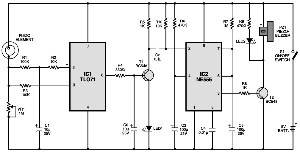
Vibration seismic sensor diagram. IC TLO71 (IC1) is wired as a differential amplifier with both its inverting and non-inverting inputs tied to the negative rail through a resistive network comprising R1, R2 and R3.
Under idle conditions (as adjusted by VR1), both the inputs receive almost equal voltages, which keeps the output low.

