
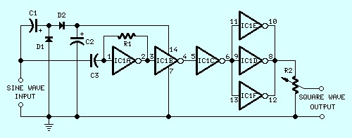
This sine wave to square wave converter circuit is expected to provide good square waves changing a sine wave delivered from an existing generator. Its primary feature consists in the fact that no power-source is required: in this manner it can be simply connected between a sine wave generator and the device under test.
The input sine wave sustains a voltage doubler formed by C1, C2, D1 & D2 that powers the IC. IC1A amplifies the input sine wave, other inverters included in IC1 squaring the signal and delivering an output square wave of equal mark/space ratio and good rise and fall times through the entire 20Hz-20KHz range.
Sine Wave to Square Wave Converter Circuit Notes:
- Minimum sine wave input amplitude needed for good performance: 750mV RMS.
- Best performances are obtained with an input sine wave amplitude from 1V RMS onwards.
- Output square wave amplitude is proportional to input amplitude.
- Output square wave amplitude with 1V RMS input: 3V peak to peak, with R2 set at max.
- Minimum output square wave amplitude: 2V peak to peak, with R2 set at max.
- Substituting the two silicon diodes with germanium types (e.g. AA118, AA119), the minimum input threshold can be lowered.
This sine wave to square wave converter come from redcircuits.com


