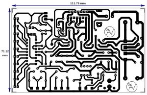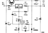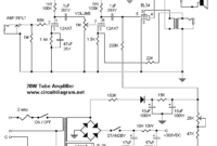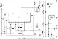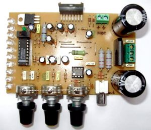
This is a very interesting circuit design to assemble. There are 4in1 amplifier module in a circuit board. 100W power amplifier using the TDA7294, for the VU meter uses IC LM3914. The tone control preamp uses the well-known IC 4558. The symmetrical power supply module also included in the PCB.
Schematic Diagram 4in1: 100W RMS Power Amplifier With VU, Power Supply and Tone Control
Part Lists
Active Components
- IC TDA 7294 : 1
- IC 7812 : 1
- IC LM3914 : 1
- Diode Zener 12V : 2
- IC 4558 : 1
- Diode 1N4148 : 1
- Rectifier Bridge Diode 6 A : 1
- LED : 11
Resistors
- 390 Ω – 1/4w : 1
- 680 Ω – 1/4w : 1
- 1K Ohm – 1/4w : 2
- 2k2 Ohm – 1/4w : 3
- 2k7 Ohm – 1/4w : 1
- 3k3 Ohm – 1/4w : 1
- 5k6 Ohm – 1/4w : 1
- 8k2 Ohm – 1/4w : 1
- 10K Ohm – 1/4w : 4
- 20K Ohm – 1/4w : 2
- 22K Ohm – 1/4w : 3
- 30K Ohm – 1/4w : 1
- 47k Ohm – 1/4w : 1
- 10R ohm – 1/4w : 1
- 56R Ohm – 2w : 1
- 2K2 Ohm – 2w : 2
- Potensiometer 50K Ohm : 3
Capacitors
- 100pF nonpolar capacitor disc / ceramic : 2
- 6n8F nonpolar polyester capacitor : 2
- 10nF nonpolar polyester capacitor : 2
- 100nF nonpolar polyester capacitor : 6
- 220nF nonpolar polyester capacitor : 1
- 2.2uF/63V electrolytic capacitor : 1
- 10uF/63V electrolytic capacitor : 5
- 22uF/63v electrolytic capacitor : 2
- 100uF/63V electrolytic capacitor : 2
- 4700uF/63V electrolytic capacitor : 2
100W RMS Power Amplifier PCB Layout
Component Placement
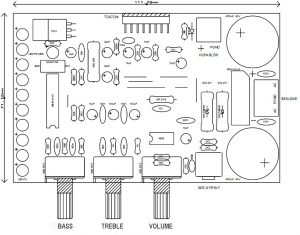
This is a single channel (mono) audio system. For stereo audio system, you need two similar circuit and make some changes such as: use higher transformer current, higher diode current, higher capacitor value for the power supply module. Use only one power supply. Use stereo potensiometer and connect to the two boards using cable.


