This is a simple, well designed 1.5 Watt FM Transmitter circuit using power transistor 2N2219A. This circuit should be able to cover 1-2 KM range. It use +5-30V power supply to work.
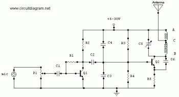
Refer to the above diagram, the input source is an electret condenser microphone (you may try to? use other input sources) and signal gain from the input can be adjusted by using the potentiometer P1. You can easily prepare the PCB by using any PCB editor and apply it to the board by using the ironing method. The coils and the antenna can be designed as a part of the PCB made up of the copper area.
Components List:
| R1=220K R2=4.7K R3,R4=10K R5=100ohm |
C1,C2=4.7uF Electrolytic C3,C4=1nF C5=2-15pF C6=3.3pF |
Q1=BC547C Q2=2N2219A P1=25K MIC=Electret Condenser Type |
P1 act as condenser microphone volume level. For FM, coil will be small. Use thin gauge enamel magnet wire. the diameter of coil will be a couple mm: use ink tube from pen to form, and try 8-12 turns. Small inductance coils make for much guess work.
Good luck.


