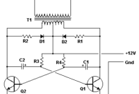
…depends the T1, T2 and transformer used. Please see the note. Basic Inverter Components list: Part Total Qty. Description Substitutions C1, C2 2 68 uf, 25 V Tantalum Capacitor R1,…
Search Results For: Fortinet ICS-SCADA Practice Test Software For Self-Evaluation 📴 Open ▷ www.pdfvce.com ◁ and search for 「 ICS-SCADA 」 to download exam materials for free 🥌ICS-SCADA Valid Test Vce
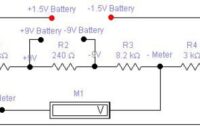
1.5V and 9V Battery Tester
Here is the circuit diagram of battery tester designed by Matthew B.. This circuit can be used to measure the 1.5V and 9V battery. The circuit is very-very simple and…
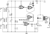
Low Cost Water Pump Controller
…fast reaction, no wear and tear, and no mechanical problems. The circuit diagram can be seen on above image. The unit performed satisfactorily on a test run in conjunction with…
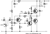
2 Watt Mini Audio Amplifier
…amplifier which can be used for computer, CD player or other devices which have headphone output. The circuit was deliberately designed using no ICs and in a rather old-fashioned manner…
Stereo Digital Volume Control
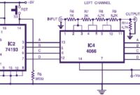
…controlling two quad bi-polar analogue switches in each of the two CD4066 ICs (IC3 and IC4). The two of the output bits, when high, short a part of the resistor…
Electronic Stopwatch
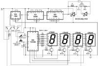
…a determination of 0.1 second. This stop-watch might be utilized for sports, games and other comparable different exercises. A 1MHz crystal produce stable frequency which is divided by two stages…
300W RMS Stereo Power Amplifier based IC TDA7294
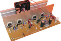
…two ICs in bridge mode. In this application, the load value must not be less than 8 Ohms. The main advantages of this solution are the following: – High power…
25W Hi-Fi Audio Amplifier based LM1875
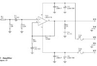
…in excess of 100dB Open loop gain typically 90dB 70mA quiescent current (typical) Download 25W Hi-Fi Audio Amplifier based LM1875 circuit kit manual: [wpdm_file id=37] Download LM1875 Datasheet: [wpdm_file id=38]…
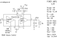
4W Audio Amplifier based TDA1013B
…TDA1013B Features: Few external components Wide supply voltage range Wide control range Pin compatible with TDA1013A Fixed gain High signal-to-noise ratio Thermal protection Download the document of TDA1013B datasheet for…
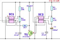
Wailing Alarm Siren
Here is the wailing alarm siren circuit diagram: Components List: R1,R5___________ 4.7K R2______________ 47K R3______________ 10K R4______________ 100K Rx______________ *see text C1,C4__________ 100uF/25V, electrolytic C2,C3__________ 0.01uF (10nF), ceramic T1_____________ 2N3702…

