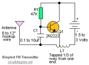
This is the simplest RF transmitter circuit diagram.
The frequency can also be changed by changing the value of C1. A 2N2222 transistor is recommended, but you can try other types also. Performance tends to vary from type to type as well as from transistor to transistor. L1 is 20 to 30 turns of thin magnet wire (24 to 32 ga.) close wound around a 1/8 to 1/4″ diameter non-conductive form. The coil is tapped 1/3 of the way from one end and the tap connected to the emitter of Q1.

