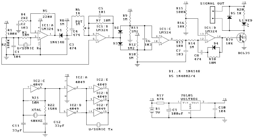
Ultrasonic motion detector circuit diagram
COMPONENTS:
Resistors: carbon film, 5%
47R – R17 : 1
1K brown black red – R6, R20 : 2
2K2 red red red – R4 : 1
10K brown black orange – R13, R16, R19 : 3
100K brown black yellow – R1, R2, R15 : 3
150K brown green yellow – R22 : 1
220K red red yellow – R5 : 1
1M Brown black green – R8, R9, R10, R14 : 4
1M2 brown red green – R12, R11 : 2
10M brown black blue – R3, R7, R18, R21 : 4
Trimpot 1M : 1
Capacitors:
100nF monoblock (104) – C1, C10 : 2
100pF monoblock (101) – C5 : 1
10nF (103) ceramic – C2, C6, C7 : 3
33pF ceramic – C11, C12 : 2
100 uF electrolytic – C9 : 1
470 nF (474) monoblock – C3, C4, C8 : 3
Diode 1N4002/4 – D5 : 1
Diode 1N4148 – D1, 2, 3, 4 : 4
9V battery snap : 1
40kHz crystal : 1
78L05 voltage regulator : 1
14049 hex buffer IC : 1
BC639 : 1
LM324 IC : 1
14 pin IC socket : 1
16 pin IC socket : 1
40kHz Ultrasonic Tx/Rx pair 400ST/R160 : 1
LED : 1

