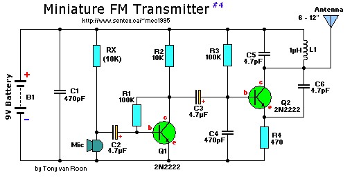
9V – 2 transistor mini FM transmitter circuit diagram
Nothing critical here. To get a bit of tuning out of the coil you could put a 4-40pF trimmer capacitor (optional) parallel over the 1 uH coil, L1. C1/C4 and C5/C6 are ceramic capacitors, preferably NPO (low noise) types. C2/C3 are electrolytic or can be tantalum types. The antenna is nothing more than a piece of 12″ wire or a piece of piano wire from 6″ to 12″.
Set your FM radio for a clear, black spot in the lower end of the band (88MHz). Then, using a non-conductive/non-metallic trimmer tool, fine-tune this capacitor to find the clearest reception. A little bit testing and patience might be in order.

