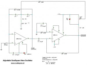
The following scheme diagram is the circuit diagram of simple easily tuned / adjustable sine and square wave oscillator. With this circuit you can easily generate sine/square wave which can be adjusted both the frequency and amplitude.
The circuit uses IC LM101A, a general purpose operational amplifier (op-amp) and IC LM111, a high-speed voltage comparator device.
This circuit provides sine and square wave at frequency of below 20Hz up to above 20KHz. The benefit of this circuit diagram is that you can adjust the output frequency by varry the variable resistor of R3. You can also adjust the amplitude of output sine/square wave by adjust the potensiometer R6.
How to define the frequency value at output line, provided on above scheme diagram image.


thank you of your good circuit