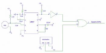
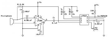
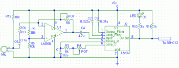
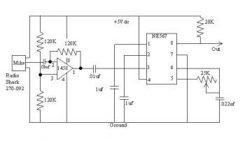
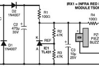
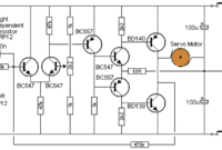
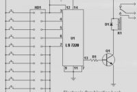
The following circuit diagrams are tone detector circuit diagrams which also known as sound activated switch circuit. Actually, these circuits? use microntroller for switching because the circuits were designed for robot start up activation. But you can build switching module using relay. You may make a trial to use this circuit for other applications such as to automatically turn on the lamp, anti theft or security applications.
Tone Detector diagram 1
Tone Detector diagram 3
Tone Detector diagram 4
Tone Detector diagram 5
Circuit source: Sound activated switch for robot

