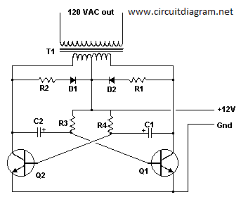
Basic Inverter Part List:
C1, C2 = 68 uf, 25 V Tantalum Capacitor
R1, R2 = 10 Ohm, 5 Watt Resistor
R3, R4 = 180 Ohm, 1 Watt Resistor
D1, D2 = HEP 154 Silicon Diode
Q1, Q2 = 2N3055 NPN Transistor (see “Notes”)
T1 = 24V, Center Tapped Transformer (see “Notes”)
MISC = Wire, Case, Receptical (For Output)
Go to main post of this image to read the detailed explanation about this circuit

