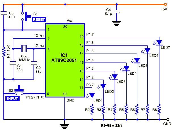
Electronic Dice Circuit Working:
The use of IC AT89C2051 (IC1) module in the design is quite simple. It operates off 3-5.5V DC supply and uses an 18MHz crystal to generate the clock (refer Fig. 2). Switch S1 connected at pin 1 is used as a reset switch. Interrupt occurs at pin 6 of IC1 on logic 0. Switch S2 connected to pin 6 (INT0) of IC1 is used to trigger an external interrupt to make pin 6 low. It is used as input to generate the random number. The random number is indicated by glowing of the LEDs (LED1 through LED7) connected to port pins P1.2-P1.7 and P3.7.

