Mini FM Transmitter Circuit Electronic
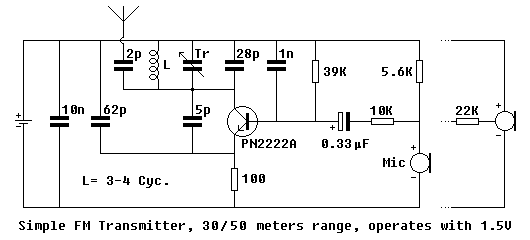
The critical part is the inductance L which should be handmade. Get an enamelled copper wire of 0.5mm (AWG24) and round two loose loops having a diameter of 4-5mm. Wire size may vary as well. Rest of the work is much dependent on your level of knowledge and experience on inductances: Have an FM radio near the circuit and set frequency where is no reception. Apply power to the circuit and put a iron rod into the inductance loops to chance it”s value. When you find the right point, adjust inductance”s looseness and, if required, number of turns. Once it”s OK, you may use trimmer capacitor to make further frequency adjustments. You may get help of a experienced person on this point. Do not forget to fix inductance by pouring some glue onto it against external forces. If the reception on the radio lost in a few meters range, than it”s probably caused by a wrong coil adjustment and you are in fact listening to a harmonic of the transmitter instead of the centre frequency. Place radio far away from the circuit and re-adjust. An oscilloscope would make it easier, if you know how to use it in this case.

