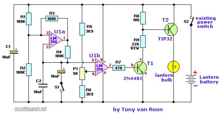
Lantern dimmer and flasher circuit
In dimmer mode (switch S1 open), the circuit send rapid variable-width pulses to the bulb to control the brightness and in flasher mode (switch S1 closed) the pulse rate is about one per second. Very short flashes will give a greatly extended battery life. The TIP32 remains cool since it switches on and off instead of simply dropping the voltage like a power rheostat.
The components are not critical and substitutions are fine. Almost any general purpose op-amps or comparators will work in place of the LM358. The two transistors may be replaced by a power FET if desired simply by connecting the gate to pin 7 of the Op-Amp, the source to ground, and the drain to the bulb. The other end of the bulb connects to the positive terminal of the battery in this case.
There is nothing particularly critical about the resistor and capacitor values and the experimenter may change them, if desired. For example, a 10K-pot may be substituted for the 5K by increasing the 3.9K resistors by 2 also (8.2K would be fine). The 100K’s in the flash circuit may be a different value if the capacitors are also scaled (inversely–if the resistors are doubled, the 0.1 and 10uF are halved).
For Q1 (2N4401), a PN100 or a BJT like the 2N3904 should work fine also. Power transistor Q2 (TIP32) can be replaced with a NTE197 or a NTE292.
Try experimenting with whatever you have at hand or combine values to get the desired value you want.

