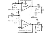
This is the diagram of 4W stereo power amplifier built based stereo power IC LM2877 with a few of external components. The circuit required single power supply with voltage range of 6VDC – 24VDC. Heatsink is […]
Circuit Schematic Diagram
Mini AM Transmitter
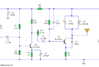
This is the simple and low cost AM transmitter schematic diagram built using transistor BC109C. The circuit is in two halfs, an audio amplifier and an RF oscillator. The oscillator is built around Q1 and associated […]
Beeper Sound
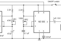
This is the circuit diagram of beeper sound. The circuit will generate the sound of a beeper which similar with the one in pagers. It produces a “beep-beep” sound. The work of this circuit is simple, […]
25W Hi-Fi Audio Amplifier based LM1875
Here the circuit diagram of 25 watt Hi-Fi (high fidelity) audio amplifier that build based on single power amplifier IC LM1875 that should be run using heatsink attached on its. Components List: R1 _____________ 1K R2 […]
1.5 Watt FM Transmitter
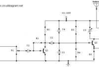
This is a simple, well designed 1.5 Watt FM Transmitter circuit using power transistor 2N2219A. This circuit should be able to cover 1-2 KM range. It use +5-30V power supply to work. Refer to the above […]
Mic Condenser Amplifier
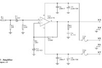
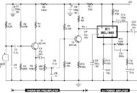
This is the circuit diagram of mic condenser amplifier. The low-cost and compact mic condenser audio amplifier described right here is deliver good-quality audio of 0.5 watts at 4.5 volts. It could possibly be applied as […]
65W Power Amplifier using HEXFET
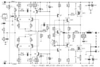
This is a high quality 65W power amplifier circuit based HEXFET IRF9540 and IRF540. The circuit is quite simple for amplifier with good sound quality. The component parts is easy to find at electronic store around […]
Sound Effects Generator (8 different sound) based IC HT2884
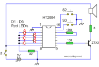
This is the circuit diagram of sound effects generator. All sounds in this circuit are generated by HT2884. The HT2884 is a CMOS LSI chip equipped with tone circuit, noise circuit, and other control logic to […]
Lead-Acid Battery Charger
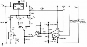
The following scheme diagram is the circuit diagram of Lead-Acid battery charger. This circuit provides an initial voltage of 2.5 V per cell at 25 ? to quickly charge the battery. The charging current decreases as […]
LED Color Fade Effect
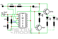
This is the circuit of LED color fade effect. Just like the name of the circuit, the light intensity of LEDs in this circuit will fade from high? intensity to low intensity and then off. Here […]

