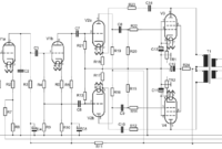
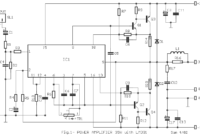
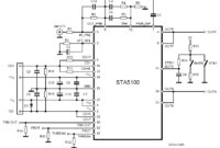
This is an audio mixer circuit which designed along with VU meter circuit. The circuit is for one channel input, if you need, for example 5 channel mixer, then you need to build 5 similar circuits. The this audio mixer uses three potensiometers to adjust volume level, low frequency (bass) level and high frequency (treble) level. You may add echo chamber circuit for better voice output.
Schematic diagram:
TR1,2 = FCS9015 ; TR3 = C1213 ; IC1,2 = 741 or TL071
This circuit need about 18 VDC power supply to work, use regulated power supply for better performance.
The kit of this circuit is available on the market, i took the picture from electronic store in my town. This circuit is absolutely works.


jaman jadul iki rek.. tahun 1990 an… pean duwe layout pcb ne?.. saturn s 90 yo..
Master mixer