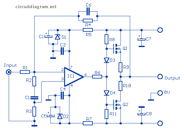
This is a small 12W audio amplifier over a load of 8 Ω, that combining the NE5534 integrated with a pair of V-MOSFET transistor output stage technology as we get excellent sound performance. MOSFET 2SK135 / 2SJ50 from Hitachi is used in this circuit. Input sensitivity of the circuit is 3V RMS maximum, the distortion factor is 0.002% at 1 kHz, and the frequency response is 15 Hz to 100 kHz. (-3dB).
This circuit requires a symmetrical (dual polarity) power supply with voltage output +/- 25V and the current output should be 2A maximum.
12W Audio Amplifier Components List:
| R1 = 33 kΩ | C1 = 1nF 63V | D1 = 1N967B zener 18V 0.5W |
| R2 = 6.8 kΩ | C2 = 47 ?uF 40V | D2 = 1N967B zener 18V 0.5W |
| R3 = 22 kΩ | C3 = 100 nF 63V | D3 = 1N4148 |
| R4 = 100 kΩ | C4 = 100 nF 63V | D4 = 1N4148 |
| R5 = 1 kΩ | C5 = 47 ?uF 40V | Q1 = 2SK135 MOSFET |
| R6 = 330 Ω | C6 = 4.7 pF ceramic | Q2 = 2SJ50 MOSFET |
| R7 = 1 kΩ | C7 = 100 ?uF 40V | IC1 = NE5534 |
| R8 = 10 kΩ | C8 = 100 ?uF 40V | |
| R9 = 0.47 Ω 2W | ||
| R10 = 0.47 Ω 2W | ||
| R11 = 10 kΩ |
Power Supply Specification:
Voltage: Symmetrical 25V
Current : 1A – 2A Max
MOSFET 2SK135 and 2SJ50 Datasheet Downloads:
Do you have a bicycle..? why don't try to build this circuit..?. Powered using battery…
This is the circuit diagram of 3A switching power supply regulator: Simple and cheap, the…
Here is the remote control tester circuit. This circuit is really a simple and easy…
This is the circuit diagram of current output multiplier designed for regulator IC LM78xx. By…
The following diagram is the FM tracking transmitter based on 4 transistors. No additional notes…
This is the circuit diagram of white line follower toy. The actuator of the toy…
View Comments
Hello.
I would be interested in the 12W Audio Amplifier based MOSFET 2SK135 / 2SJ50.
I would like to make this printed circuit amplifier so I would like to know if you have its PCB or its design available.
Thank you
Pasquale