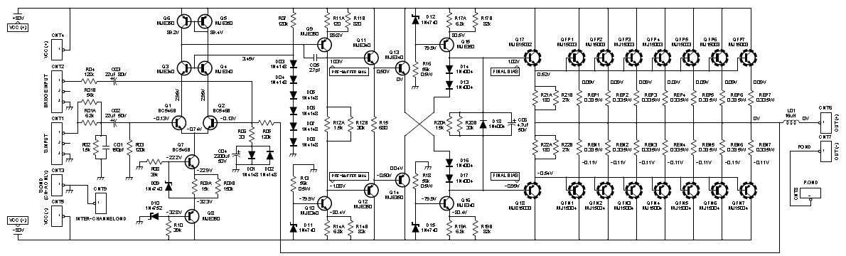
This is the circuit diagram of 2000W class AB power amplifier uses 7 pairs MJ15003 and MJ15004 transistors for the final amplification block. The circuit operated with 90V DC symmetrical (dual polarity) power supply circuit. The transistors must be mounted on heatsink to prevent the overheating, maintain the transistors work in maximum performance.
2000W Class AB Power Amplifier Specifications:
Download the schematic diagram in PDF document for higher image resolution:
Goodluck 🙂
Do you have a bicycle..? why don't try to build this circuit..?. Powered using battery…
This is the circuit diagram of 3A switching power supply regulator: Simple and cheap, the…
Here is the remote control tester circuit. This circuit is really a simple and easy…
This is the circuit diagram of current output multiplier designed for regulator IC LM78xx. By…
The following diagram is the FM tracking transmitter based on 4 transistors. No additional notes…
This is the circuit diagram of white line follower toy. The actuator of the toy…
View Comments
NICE WORK
sir iwant pcb pdf and power supply ampears?
please send the clear resolution circuit diagram of 2000w class AB amplifier and its power supply diagram to my email. thank you for the information
Dear sir I am new bee to power amplifiers , can u please provide me PCB print design and how much power supply does it requires , I want to make amp for my village people ....
Kindly help me in this issue
GOOD DAY!!!
SIR, HOW TO GET THE FOIL PATTERN OF PCB 2000 WATTS CLASS AB POWER AMPLIFIER PLEASE ADVICE THANK YOU.....
I Just want to mention that the complementary pair MJ15003/MJ15004 have a Vceo of 140 V. However, according to the schematic, the power rail is +/- 90 V, and the output peak voltage is 65 V. So, for a short period of time, the Vce will be equal to the addition of both, which means 155 V. If you are bad-lucky and you have some weak transistors, you can break down the emitter-collector junction...and destroy them.
Beside that, this transistor is very tough, I build myself, many years ago, a 300 Watts RMS on 4 Ohms load power amplifier that use 3 pairs at the output stage.
Sir,
Please give me the pcb component layout of 2000W class AB amplifier.
Regards,
Jerin.
Hi Sir request u to kindly send the PCB file pattern of 2000 watts power amp class AB
Dear friend
Can you please send me the power supply diagram and PCB if you have made it.
sir, can u send me a copy of foil pattern in my FB account